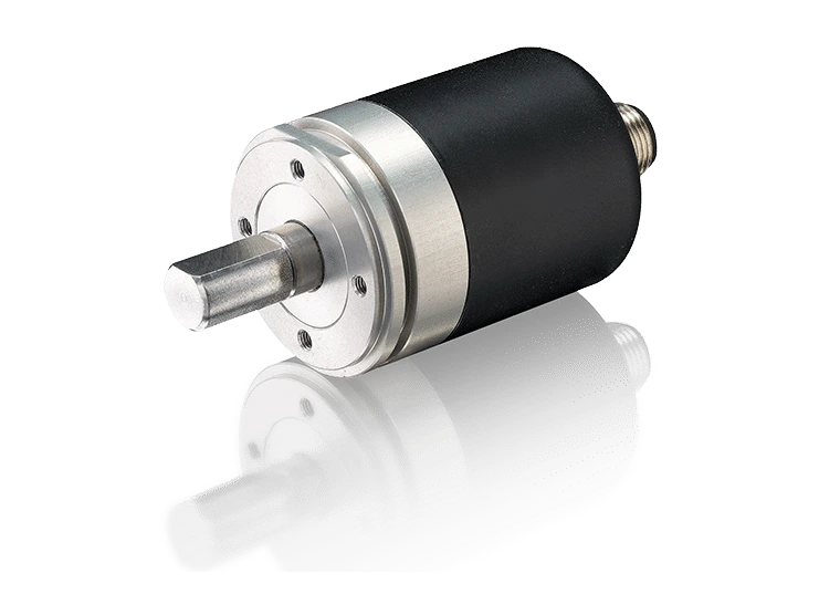
MB1-3600 IO-Link Multiturn Magnetic Absolute Encoder
Novotechnik MB1-3600 IO-Link Magnetic Absolute Encoder. Non-contact magnetic multi-turn sensor.
True-Power-On magnetic multi-turn absolute rotary encoder (GMR magnetoresistive technology), contactless. Ø36 mm, metal housing, double bearing. Measuring range 44 revolutions (15840°), resolution 16 bits per revolution. Heavy-duty version with IP69K protection. Hollow shaft version with integrated stator coupling.
Key points
- Contactless, magnetic
- True-Power-On System: Counts laps even without power; patented non-volatile technology, no gears or batteries
- Solid shaft or hollow shaft
Technical Frequently Asked Questions
What can be connected to the MB1-3600 IO-Link magnetic absolute encoder?
It can be connected to Novotechnik M12 connectors and cables and Novotechnik rotary sensor couplings and accessories.
How do I order the MB1-3600 IO-Link magnetic absolute encoder?
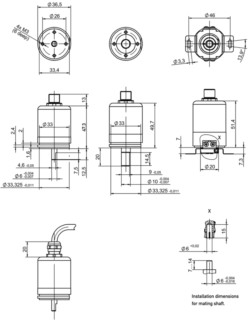
The order code has 5 fields: mechanical version, revolutions, interface, parameters, and connection. For example, MB1-3601-244-A11-FN4 is the synchronous flange version with a Ø6 mm x 12.5 mm shaft, 44 revolutions (15840°), IO-Link with one clockwise increment, and a 4-pin M12x1 connector. All the options for each field are available in the order code configurator on this page.
Under what conditions does the MB1-3600 IO-Link magnetic absolute encoder operate?
Operating temperature: -30 … +85 °C.
Properties
| Feature | Specification |
|---|---|
| Extent | |
| Measured variables | Position, speed, temperature, and supply voltage |
| Number of channels | 1 |
| Measuring range | 44 turns (15840°) |
| Speed measurement range | 0 … 546 rpm |
| Linearity | ≤ ±1° |
| Repeatability | ≤ ±0.1° |
| Hysteresis | ≤ ±0.5° |
| Temperature error | ±0.36° |
| Interface and protocol | |
| Protocol | IO-Link Spec V1.1 according to IEC 61131-9, Smart Sensor Profile Ed. 2 Digital Measuring Sensor SSP 4.2.1 (compatible with V1.0) |
| Position resolution (in 360°) | A11/A12: 16 bits, A10: 0.01°/LSB |
| Speed resolution | 0.1°/s |
| Update frequency | 1 kHz |
| Signal propagation delay | < 0.2 ms |
| Transmission speed | COM 3 (230.4 kBaud) |
| Type of plot | 2,2 |
| Minimum cycle time | 1 ms |
| Functions and supervision | |
| Programmable parameters | e.g. zero point offset, resolution, direction of rotation, switches, working area, operating modes |
| State oversight functions | Statistical data on temperature, operating time, supply voltage, and operating performance |
| Start-up time | ≤ 120 ms |
| Diagnosis | Activated (in case of error, the position signal falls outside the plausible signal range) |
| Feeding and protection | |
| Supply voltage Ub | 24 VDC (16 … 30 VDC) |
| No-load current consumption | ≤ 30 mA at 24 V |
| Power consumed without load | < 0.72 W |
| Reverse polarity protection | Yes (power lines and outlets) |
| Short circuit protection | Yes (output to GND and supply voltage up to 40 VDC) |
| Overvoltage protection | 36 VDC (permanent) |
| Insulation resistance (500 VDC) | ≥ 10 MΩ |
| Environmental conditions | |
| Working temperature | -30 … +85 °C |
| Vibration IEC 60068-2-6 | 20 g, 5 … 2000 Hz, Amax = 0.75 mm |
| IEC 60068-2-27 Shock | 50 g, 6 ms |
| Insensitivity to DC magnetic fields | < 15 mT |
| Bearing life | typical > 100 million movements |
| MTTF (IEC 60050) | 591 years |
| Electromagnetic compatibility | |
| IO-Link interface and system | V1.1.3 |
| EN 61000-4-2 ESD (contact/air discharge) | 4 kV, 8 kV |
| EN 61000-4-3 Electromagnetic fields (RFI) | 10 V/m |
| EN 61000-4-4 Fast transients (burst) | 2 kV |
| EN 61000-4-6 Conducted disturbances (HF fields) | 10 V ef. |
| EN 55016-2-3 Radiated disturbances | Industrial and residential area |
| Materials and general data | |
| Flange | Anodized aluminum AlSiMgBi |
| Cover | Galvanized steel ST 12 (no. 1.0330) |
| Axis | Stainless steel X10CrNiS18-9 (No. 1.4305) |
| Stator coupling (hollow shaft version) | Stainless steel X10CrNiS18-8 (No. 1.4310) |
| Bearings | Double bearing system |
| Electrical connection | M12x1 connector, A encoding |
| Mechanical tour | Continuous |
| Weight (without connection) | approx. 100 g |
| Connection assignment | |
| Sign | M12 connector |
| Supply voltage Ub (L+) | Pin 1 |
| GND (L-) | Pin 3 |
| C/Q | Pin 4 |
| Do not connect (alt. GND) | Pin 2 |
| Option | Meaning |
|---|---|
| Example: MB1-3601-244-A11-FN4 = synchronous flange with Ø6 mm x 12.5 mm shaft, 44 turns (15840°), IO-Link with 1 clockwise increasing position and 4-pin M12x1 connector. | |
| 1 · Mechanical version | |
| 3601 | Synchro flange, shaft Ø6 mm x 12.5 mm |
| 3624 | Synchro flange, heavy duty, shaft Ø10 mm x 20 mm |
| 3607 | Round flange, hollow shaft Ø6 mm |
| 2 · Turns of the output characteristic | |
| 244 | Measuring range: 44 turns (15840°) |
| 3 · Interface | |
| TO | IO-Link |
| 4 · Interface parameters | |
| 10 | 1x position (SSP 4.2.1 Ed.2), increasing clockwise |
| 11 | 1x position, increasing clockwise |
| 12 | 1x position, 1x speed, increasing clockwise |
| 5 · Electrical connection | |
| FN4 | M12x1 4-pin connector |
| The code is formed using one option from each field, in the order shown in the example. Contact us and we will confirm the exact reference. | |
Related documentation, cases, and guides
Technical documentation
- Novotechnik General Catalogue: Linear and Angular Position Sensors
- Technical definitions of potentiometers: linearity, RGV and hysteresis
- Novotechnik position sensors with IO-Link interface
- Position sensors for valves and actuators: Novotechnik series
- Novotechnik linear and rotary sensors for automotive applications
Other products