




















TEX with return spring Novotechnik | Linear probe
- Manufacturer: Novotechnik
- Category: Displacement, SENSORS, Potentiometric linear sensors
He TEX with return spring Novotechnik it's a potentiometric linear probe designed to absolutely measure the displacement, position, or stroke of a part by direct contact. Unlike a transducer with a stem mechanically attached to the moving element, the spring keeps the probe tip supported on the surface and automatically returns the stem, allowing measurement without a fixed connection to the part.
Physically, the sensor consists of a longitudinal anodized aluminum casing, a stainless steel axial stem and a helical return spring around the sensing zone. At the end it incorporates a probing tip with M2.5 thread and carbide ball. This configuration allows tracking the movement of surfaces, profiles, or components that come into contact with the probe.
This page specifically corresponds to the execution TEX with automatic spring return. This is not the standard TEX free-stemming version, as the moving element does not need to be permanently fixed to the stem. It is available with defined strokes starting from 10 to 200 mm and can be installed by two adjustable clamps or by M10 central fixing, the latter available up to 150 mm.
The series offers independent linearity of up to ±0.05 % FS, repeatability of 0.01 mm When the stem is working without lateral loads, the maximum speed of 5 m/s and a maximum operating frequency in the center position of up to 49 Hz, depending on the route. Its typical lifespan exceeds 50 million movements, according to the application conditions.
- Technology: conductive plastic potentiometric.
- Type of measurement: absolute linear position and displacement by contact.
- Return: automatic by spring.
- Moving element: axial stem with probing tip.
- Tip: M2.5 external thread with carbide ball.
- Defined routes: 10 / 25 / 50 / 75 / 100 / 125 / 150 / 175 / 200 mm.
- Exit: voltage divider · ratiometric signal.
- Mounting: adjustable clamps or M10 center fixing up to 150 mm.
- Independent linearity: up to ±0.05 % FS depending on the route.
- Repeatability: 0.01 mm without side loads.
- Horizontal drive force: 5.6 ±0.8 N at 20 °C.
- Maximum frequency: 20…49 Hz depending on the path.
- Maximum speed: 5 m/s.
- Protection: IP54.
- Operating temperature: −40…+85 °C.
- Connection: M8x1 connector or 2 or 5 m shielded PUR cable, with radial or axial output depending on the reference.
TEX applications with return spring
Automatic return allows you to use TEX as displacement probe This method is used when it is necessary to measure a position by contact without mechanically fixing the probe to the workpiece. The sensor follows the movement of the surface while the spring keeps the probe tip in contact.
Dimensional control and parts tracking
- Measurement of displacements by direct contact.
- Tracking of profiles, surfaces, and moving components.
- Checking initial, final and intermediate positions.
- Dimensional verification and race control.
- Repetitive measurements on tooling and control devices.
Machinery and automation
- Position control of moving components.
- Displacement feedback in machines and automatic systems.
- Measurement without permanent mechanical connection between the sensor and the part.
- Linear motion tracking with automatic probe return.
Test benches and laboratory
- Displacement recording during mechanical tests.
- Verification and dimensional measurement equipment.
- Repetitive motion tests.
- Displacement measurement along with force, pressure, torque, or other variables.
The threaded tip M2,5 It also facilitates the use of compatible probe tips when the geometry of the application requires a different form of contact.
How the return spring works
The element whose position is to be measured acts directly on the probe tip. As the part moves, the stem enters the sensor body and internally moves the potentiometric cursor.
When the piece moves in the opposite direction or stops pressing the tip, the return dock The stem is then moved back to its extended position. This eliminates the need to rigidly connect the sensor to the component being measured.
The specified horizontal drive force is 5.6 ±0.8 N at 20 °C. This force must be taken into account when measuring lightweight, flexible, or pressure-sensitive components.
Uncontrolled release of the spring against the internal stops should be avoided, and the stem should not be lubricated.
M2.5 probe shaft and tip
The stem is made of stainless steel 1.4305 / AISI 303. At its end, a stainless steel probing tip is installed with M2.5 external thread and a pressed hard metal ball.
The M2.5 thread allows the contact element to be adapted to the mechanical needs of the application using compatible probe tips.
To maintain the specified repeatability and avoid irregular wear, the movement must be performed aligned with the longitudinal axis of the sensor and without transmitting significant lateral loads to the stem.
Maximum operating frequency according to route
The dynamics of the return system depend on the selected path. The maximum frequency specified in the center position is:
- 10 mm: 49 Hz.
- 25 mm: 43 Hz.
- 50 mm: 35 Hz.
- 75 mm: 28 Hz.
- 100 mm: 24 Hz.
- 125 mm: 21 Hz.
- 150 mm: 20 Hz.
- 175 mm: 20 Hz.
- 200 mm: 20 Hz.
These values correspond to the maximum frequency indicated for the center position. Actual performance also depends on the stroke used and the mechanical conditions of the application.
Potentiometric output and absolute measurement
The TEX with return spring is a linear potentiometric transducer. The movement of the probe displaces a multi-wire cursor of precious metal on a resistive track of conductive plastic.
The sensor should be used as voltage divider with virtually no load on the cursor. The signal obtained is ratiometric and proportional to the mechanical position of the probe.
Depending on the selected path, the nominal resistance is between 1 and 8 kΩ. The recommended current across the cursor is less than 1 µA and the maximum permissible voltage is 42 VDC.
It does not directly incorporate a standard industrial output of 0–10 V or 4–20 mA. When the PLC, indicator, or acquisition system requires one of these signals, a compatible signal conditioner can be used.
Since it is an absolute measurement, the probe position is obtained directly from the potentiometric signal and it is not necessary to perform a reference search after a disconnection.
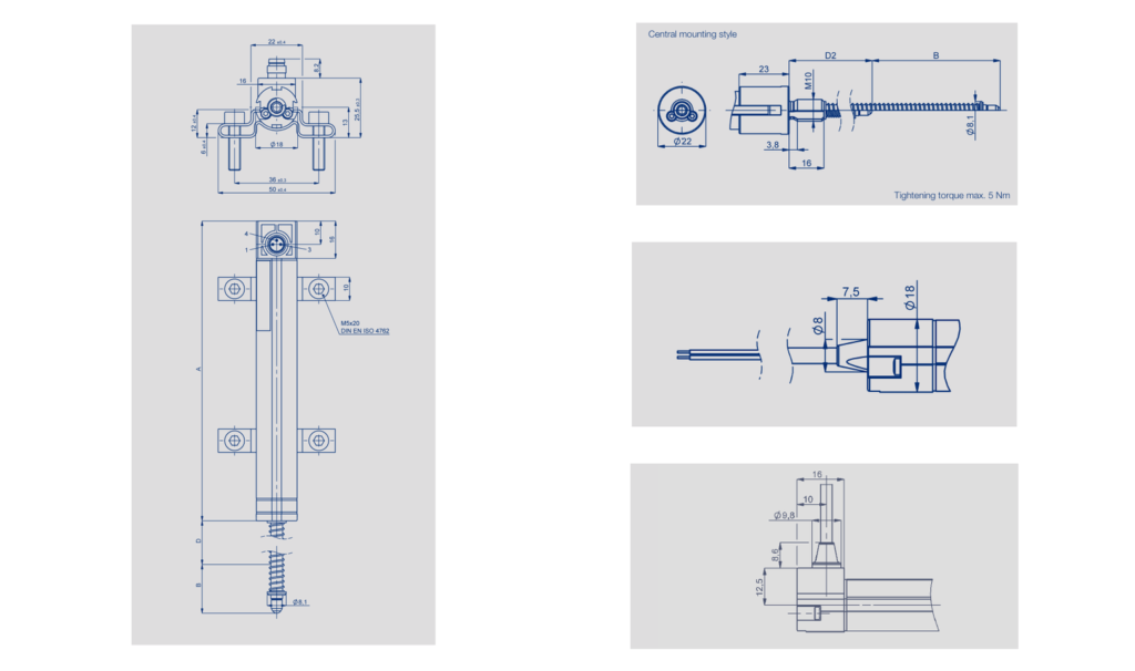
Mounting using clamps or M10 central fixing
The family is available with two mechanical versions:
- 421 · Return spring + clamps: Available for travel distances from 10 to 200 mm. Two clamps and four M5x20 screws are supplied.
- 428 · Return spring + M10 center mount: Available for travels from 10 to 150 mm. The maximum tightening torque on the collar is 5 Nm.
Clamp mounting allows the sensor body to be attached directly to a structure or support. The version with an M10 center thread allows it to be passed through a mounting plate or bracket and the probe's position relative to the workpiece to be adjusted.
M8x1 connector and versions with PUR cable
The type of electrical connection is defined by the last three digits of the reference:
- 101: M8x1 3-pole radial connector.
- 202: 2m shielded PUR cable, radial output.
- 205: 5m shielded PUR cable, radial output.
- 302: 2m shielded PUR cable, axial output.
- 305: 5m shielded PUR cable, axial output.
Electrical allocation
- End of track 1: pin 1 / BN · brown.
- Cursor signal: pin 4 / WH · white.
- End of track 3: pin 3 / GN · green.
In versions with an integrated cable, the display must be grounded. Pin 4 corresponds to the cursor signal, and pins 1 and 3 correspond to the ends of the resistive trace.
References and configuration of the Novotechnik TEX with return spring
The reference is constructed following the format:
TEX-RRRR-MMM-002-CCC
- RRRR: route: 0010 / 0025 / 0050 / 0075 / 0100 / 0125 / 0150 / 0175 / 0200.
- MMM = 421: return spring and mounting using clamps.
- MMM = 428: return spring and M10 center mount, available up to 150 mm.
- 002: linearized resistive element, standard version.
- CCC: connection code 101 / 202 / 205 / 302 / 305.
Example: TEX-0100-421-002-101 corresponds to a 100 mm TEX with return spring, clamp mounting and M8x1 radial connector.
Example: TEX-0150-428-002-202 corresponds to a 150 mm TEX with return spring, M10 central fixing and 2 m shielded radial PUR cable.
Frequently asked questions about the TEX with return spring
What is the difference between the TEX with spring and the standard TEX with stem?
He TEX standard with stem It connects mechanically to the element whose position is to be measured. In this version, the spring automatically pushes the probe against the part, so the measurement can be performed by contact without a fixed mechanical connection.
What tours are available?
The defined travel distances are 10, 25, 50, 75, 100, 125, 150, 175 and 200 mm.
What force does the probe exert?
The specified horizontal drive force is 5.6 ±0.8 N at 20 °C. It must be verified that the part can withstand this force without appreciable displacement or deformation.
Does the TEX directly deliver 0–10 V or 4–20 mA?
No. It is a passive potentiometric sensor used as a voltage divider. To obtain 0–10 V or 4–20 mA, a suitable signal conditioner must be added.
Can the probe tip be replaced?
The end uses an M2.5 thread and allows the use of probe tips compatible with this mechanical connection.
Can it be used for repetitive movements?
Yes. The typical lifespan indicated is over 50 million movements, depending on the application. The maximum frequency for each movement must also be respected, and the spring must not be allowed to impact the internal stops uncontrollably.
Selection of the TEX with return spring
He Novotechnik TEX with return spring It is especially suitable when you need to perform a Absolute linear measurement by contact and without fixed mechanical connection to the workpiece.
To select the reference, the required travel, the permissible contact force, the operating frequency, the mounting system using clamps or M10, the type of electrical connection, and the geometry of the probe tip must be defined.
When the moving element can be connected directly to the sensor and automatic return is not required, the following can be used: TEX standard with stem.
Consult us for the application to select the most suitable TEX execution and reference.
Properties
| NOVOTECHNIK TEX TECHNICAL SPECIFICATIONS WITH RETURN SPRING | |
|---|---|
| Model | Novotechnik TEX with return spring |
| Sensor type | Linear displacement potentiometric probe/transducer with automatic return |
| Measurement principle | Potentiometric · conductive plastic · absolute measurement by contact |
| Return system | Automatic return spring |
| Defined routes | 10 / 25 / 50 / 75 / 100 / 125 / 150 / 175 / 200mm |
| Electric circuits | 12 / 27 / 52 / 77 / 102 / 130 / 155 / 180 / 205mm |
| Exit | Voltage divider · ratiometric signal |
| Nominal resistance according to travel | 1 / 1 / 2 / 3 / 4 / 5 / 6 / 7 / 8 kΩ |
| Resistance tolerance | ±20 % |
| Independent linearity | 10 mm: ±0.25 % FS · 25 mm: ±0.20 % FS · 50–100 mm: ±0.10 % FS · 125–200 mm: ±0.05 % FS |
| Repeatability | 0.01 mm · without side loads |
| Recommended cursor current | < 1 µA |
| Maximum cursor current in case of failure | 10 mA |
| Maximum allowable voltage | 42 VDC |
| Effective thermal coefficient | Typ. 5 ppm/K |
| Insulation resistance | > 10 MΩ at 500 VDC |
| Dielectric strength | < 100 µA at 500 VAC / 50 Hz |
| MECHANICAL DATA | |
| Housing | Anodized aluminum |
| Stem | Stainless steel 1.4305 / AISI 303 |
| Probe tip | Stainless steel · M2.5 external thread · pressed carbide ball |
| Resistive element | Conductive plastic |
| Cursor | Precious metal multi-strand |
| Horizontal drive force | 5.6 ±0.8 N at 20 °C |
| Body length A | 63 / 78 / 103 / 128 / 153 / 194 / 219 / 244 / 269 mm · depending on travel · ±2 mm |
| Mechanical Engineering B | 14 / 29 / 54 / 79 / 104 / 132 / 157 / 182 / 207 mm · ±2 mm |
| Dimension D | 25 / 25 / 50 / 75 / 95 / 98 / 105 / 113 / 121 mm · ±2 mm |
| Dimension D2 | 41 / 41 / 50 / 75 / 95 / 98 / 105 mm · up to 150 mm of travel · ±2 mm |
| Maximum frequency in central position | 49 / 43 / 35 / 28 / 24 / 21 / 20 / 20 / 20 Hz, depending on the path |
| Assembly 421 | Return spring + two adjustable clamps · travels 10…200 mm |
| Assembly 428 | Return spring + M10 central fixing · travels 10…150 mm · maximum torque 5 Nm |
| ENVIRONMENTAL DATA | |
| Working temperature | -40…+85 °C |
| Working humidity | 0…95 % HR, non-condensing |
| Vibration · IEC 60068-2-6 | 20 g · 5…2000 Hz · maximum amplitude 0.75 mm |
| Shock · IEC 60068-2-27 | 50 g · 6 ms |
| Typical useful life | > 50 × 106 movements, depending on the application |
| Maximum speed | 5 m/s |
| Degree of protection | IP54 according to DIN EN 60529 |
| ELECTRICAL CONNECTION | |
| Code 101 | M8x1 3-pole radial connector |
| Code 202 | 2m shielded PUR cable · radial exit |
| Code 205 | 5m shielded PUR cable · radial exit |
| Code 302 | 2m shielded PUR cable · axial output |
| Code 305 | 5m shielded PUR cable · axial output |
| REFERENCE CONFIGURATION | |
| Format | TEX-RRRR-MMM-002-CCC |
| RRRR · route | 0010 / 0025 / 0050 / 0075 / 0100 / 0125 / 0150 / 0175 / 0200 |
| MMM · assembly | 421 · spring + clamps / 428 · spring + M10 central fixing up to 150 mm |
| 002 · electric version | Linearized resistive element, standard |
| CCC · connection | 101 / 202 / 205 / 302 / 305 |

Other products