
Schreiber LVDT Converters and Conditioners
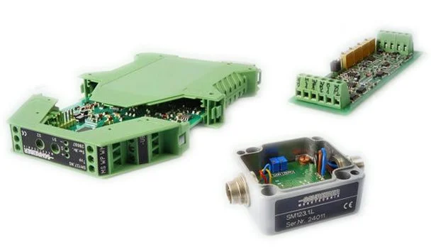
The Schreiber LVDT conditioners and converters They provide the necessary electronics to excite, demodulate, and convert the signal. LVDT and inductive half-bridge sensors in standard analog signals that can be used in PLCs, data acquisition systems, indicators, and industrial control equipment.
Schreiber Messtechnik offers various electronic modules depending on the power supply and output signal required. The range includes solutions for 0-20 mA, 4-20 mA, 0-10 V and ±10 V, as well as electronics for one or more sensors depending on the series and configuration.
Quick selection of Schreiber electronics:
- SM101: conditioner with 0-20 mA output.
- SM103: conditioner with 4-20 mA output.
- SM105: air conditioner with ±10 V output.
- SM12Configurable family with outputs 0-20 mA, 4-20 mA, 0-10 V or ±10 V depending on the version, available for one or two channels.
- SM17: ASIC developed by Schreiber for precision circuits with inductive sensors.
Availability, power supply, number of channels, and compatibility must be checked for each specific reference.
What is an LVDT signal conditioner used for?
A passive LVDT does not directly deliver an industrial signal such as 4-20 mA or 0-10 V. The transducer needs a adequate electrical excitation and an electronics capable of interpreting the variation of the signal produced by the displacement of the core.
The conditioner performs three main functions:
- Sensor excitation: provides the alternating signal necessary for the operation of the inductive transducer.
- Demodulation and amplification: It interprets the signal from the sensor and converts it into a magnitude proportional to the position.
- Conversion to a standard signal: It generates an output such as 4-20 mA, 0-10 V or ±10 V that can be used in the control system.
LVDT half-bridge and compatible electronics
Schreiber inductive sensors typically operate with an architecture of inductive half-bridge. This configuration is part of LVDT technology, but its electrical scheme and conditioning must be compatible with the specific type of transducer.
For this reason, it is not advisable to select a signal conditioner solely based on its output signal. The following should also be checked: excitation, coil configuration, sensitivity, and electrical characteristics of the sensor.
You can browse our range of Unamplified LVDT and the general category of LVDT sensors.
Which output should I choose: 4-20 mA, 0-10 V or ±10 V?
The output signal must be selected according to the equipment to which the conditioner will be connected, the wiring distance, and the requirements of the measurement system.
| Exit | Regular use | Schreiber families |
|---|---|---|
| 0-20 mA | Analog current systems and compatible measuring equipment. | SM101 / SM12 versions |
| 4-20 mA | PLC, industrial automation and current signal transmission. | SM103 / SM12 versions |
| 0-10 V | PLC analog inputs, data acquisition and control. | SM12 versions |
| ±10 V | Bipolar measurement with respect to the zero point and compatible acquisition systems. | SM105 / SM12 versions |
The required output must also be checked in conjunction with the available power supply and the input range of the PLC or acquisition system.
Schreiber SM12: Flexible conditioning for LVDT sensors
The series Schreiber SM12 It is one of the most versatile solutions in the range for working with inductive transducers.
According to this version, it allows you to obtain the following outputs:
- 0-20 mA
- 4-20 mA
- 0-10 V
- ±10 V
The series uses the Schreiber SM17 ASIC and can be configured to operate with one or two inductive transducers. The gain can be preset and fine-tuned using the electronic adjustment elements.
There are also versions prepared for DIN rail mounting, suitable for integration into electrical panels and automation cabinets.
Consult the Technical specifications of the LVDT Schreiber SM12 conditioner to check versions, power supply, wiring and specific features.
LVDT system zero and gain adjustment
In an LVDT system, the mechanical travel of the sensor must be correctly related to the electrical range that the control equipment will use.
Schreiber conditioning modules allow, depending on the model, adjustment of the zero point and profit. In this way, the mechanical position of the sensor can be adapted to the analog range required by the PLC or acquisition system.
The specific adjustment procedure depends on the air conditioner and the connected sensor, so the data from the corresponding technical data sheet should be used.
How to connect an LVDT to a PLC
An LVDT without integrated electronics typically does not connect directly to a standard analog PLC input. The usual configuration is:
LVDT → signal conditioner → 4-20 mA / 0-10 V / ±10 V → PLC
The conditioner provides excitation to the sensor, interprets the inductive signal, and generates an output compatible with the PLC's analog module.
When using a sensor with integrated electronics, the output of the transducer itself can be connected directly to a compatible input, without the need for a separate external conditioner.
To make the connection, always check the power supply, ground, polarity, output type and terminal diagram of the reference used.
How to choose an LVDT conditioner
To correctly select the electronics, both the characteristics of the sensor and those of the control system must be known.
- LVDT type and reference.
- Electrical configuration: half bridge, full bridge or other architecture.
- Sensitivity and excitation required by the transducer.
- Required output: 0-20 mA, 4-20 mA, 0-10 V or ±10 V.
- Power supply available at the panel.
- Number of channels.
- Mounting type: plate, DIN rail or other integration.
- PLC or acquisition system input range.
If you are replacing old electronics, it is advisable to have the sensor reference, the model of the existing air conditioner, and the wiring diagram.
Frequently Asked Questions about LVDT Conditioners
What is the difference between an LVDT and its signal conditioner?
The LVDT is the sensing element that detects displacement. The conditioner provides the necessary electrical excitation and interprets the transducer signal to convert it into an output usable by the control system.
Can I convert the signal from an LVDT to 4-20 mA?
Yes, provided a transducer-compatible conditioner is used. Schreiber offers solutions such as the SM103 and certain SM12 versions with 4-20 mA output.
Do all LVDT conditioners work with any sensor?
No. The sensor's electrical configuration, excitation, sensitivity, module power supply, and required output signal must be checked. A half-bridge sensor requires electronics compatible with that architecture.
Can the Schreiber SM12 work with two sensors?
The SM12 family is available in configurations for one or two inductive transducers. The specific version must be selected according to the number of channels and the required output.
Can the SM12 be mounted on a DIN rail?
Yes. Schreiber offers versions of the SM12 series designed for standard DIN rail mounting, intended for integration into electrical cabinets and panels.
What data does GUEMISA need to select the conditioner?
The sensor reference, its technical data sheet if available, the type of signal required, available power supply, number of channels and characteristics of the PLC or acquisition equipment input.
Selection and replacement of electronics for LVDT sensors
GUEMISA can help select the Signal conditioner suitable for Schreiber LVDT and inductive sensors, both for new installations and for replacing existing electronics.
If you need to identify an alternative, please send us the Reference of the sensor and current module, technical data sheet, photograph or wiring diagram, along with the signal you need to obtain.
Products: 1