




















TEX with Novotechnik ball joints | Linear position sensor
- Manufacturer: Novotechnik
- Category: Displacement, SENSORS, Potentiometric linear sensors
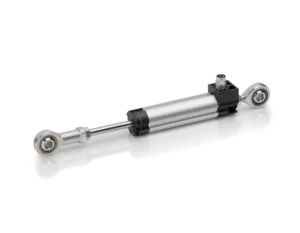
He TEX with ball joints Novotechnik it's a potentiometric linear position sensor Designed to measure the absolute and direct displacement, position, or stroke of linear mechanisms. It is available with defined travels starting from 10 to 300 mm and provides a ratiometric signal via a resistive track of conductive plastic.
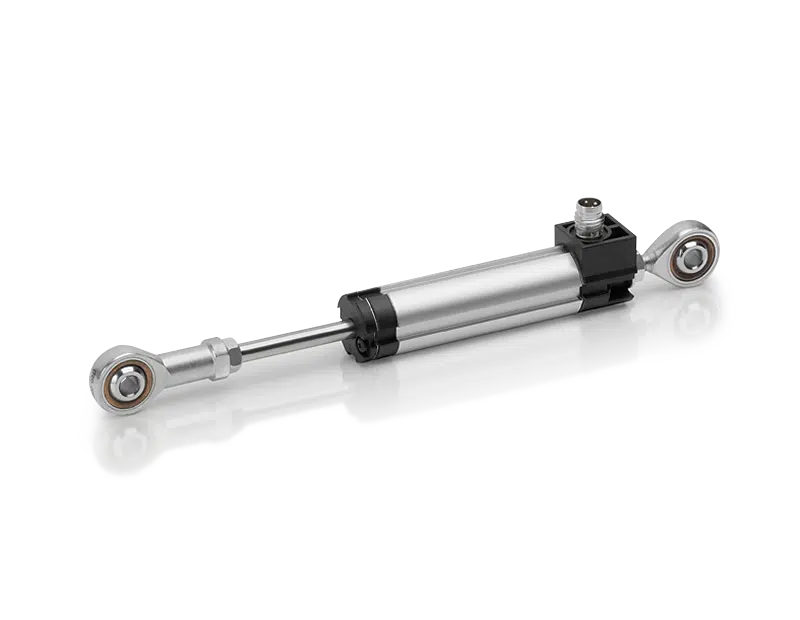
Physically, this implementation of TEX consists of a longitudinal anodized aluminum casing, a stainless steel axial stem and two articulated fixing joints, located at the points where the sensor connects to the machine or mechanism. The ball joints allow for an angular movement of up to ±12.5°, facilitating assembly when the two fixing points do not remain perfectly aligned during movement.
This page specifically corresponds to version TEX with ball joint mounting. Unlike the standard TEX secured by clamps or central mounting, this version is installed between two articulated points. It does not incorporate a return spring: the movement of the mechanism is transmitted directly to the stem between both fixing points.
There are two mechanical configurations: short ball joints, version 415, with dimension D of 18 mm, and long ball heads, version 413, with a D dimension of 25 mm. Both are available for travels from 10 to 300 mm.
The series offers independent linearity of up to ±0.05 % FS, repeatability ≤ ±0.01 mm, maximum travel speed of 10 m/s and a typical service life exceeding 100 million movements, Depending on the application. The horizontal drive force is ≤ 3 N at 20 °C.
- Technology: conductive plastic potentiometric.
- Type of measurement: absolute linear position and displacement.
- Construction: longitudinal housing with axial stem and two fixing ball joints.
- Angular motion: up to ±12.5°.
- Defined routes: 10 / 25 / 50 / 75 / 100 / 125 / 150 / 175 / 200 / 250 / 300 mm.
- Exit: voltage divider · ratiometric signal.
- Short kneecaps: version 415 · D = 18 mm.
- Long kneecaps: version 413 · D = 25 mm.
- Independent linearity: up to ±0.05 % FS depending on the route.
- Repeatability: ≤ ±0.01 mm.
- Maximum speed: 10 m/s.
- Protection: IP54.
- Operating temperature: −40…+85 °C.
- Connection: M8x1 3-pole connector or 2 or 5 m shielded PVC cable.
Applications of the TEX linear position sensor with ball joints
The ball-and-socket mounting is particularly suitable when it is necessary to measure a linear displacement between two fixing points that may present small angular misalignments. The joint prevents these deviations from having to be absorbed directly by the stem.
Industrial machinery and automation
- Absolute measurement of position and displacement.
- Position feedback in linear mechanisms.
- Stroke control of moving elements.
- Articulated assemblies between structures and moving components.
- Applications with angular variations between fixing points.
Process machinery
- Plastic injection molding machines.
- Textile machinery.
- Packaging equipment.
- Sheet metal working machines.
- Woodworking machines.
Test benches and articulated mechanisms
- Position recording during linear movements.
- Repetitive motion tests.
- Displacement measurement in mechanisms where alignment varies during travel.
- Applications that require high speed and long mechanical life.
Articulated assembly using two ball joints
The TEX is supplied with two ball joints and two locknuts. Each attachment point can be articulated, allowing up to an angular freedom of movement. ±12.5°.
This design simplifies assembly when the mechanical axes of the two mounting points are not perfectly aligned. The joint also helps reduce lateral loads that could be transmitted to the stem in a rigid mounting.
The standard ball joints are made of steel. For corrosive environments, there is a conversion kit with stainless steel ball joints for the short 415 version.
Short ball heads 415 and long ball heads 413
The TEX with articulated mounting is available in two versions:
- Version 415: short ball joints, dimension D = 18 mm.
- Version 413: long ball joints, dimension D = 25 mm.
The difference between the two versions modifies the minimum distance between the centers of the ball joints:
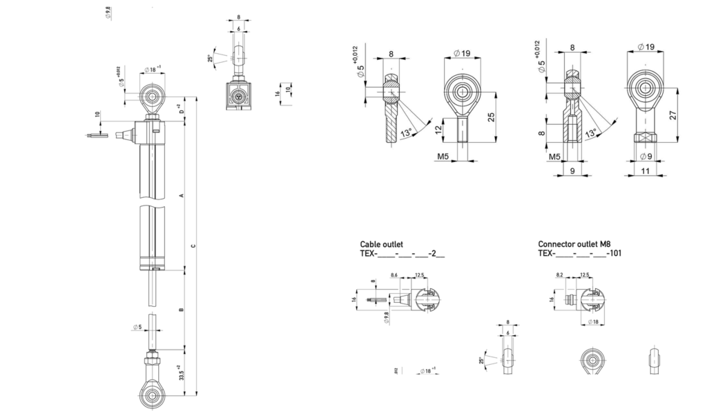
- Version 415: C minimum = A + 51.5 mm.
- Version 413: C minimum = A + 58.5 mm.
Both versions are available for all defined travels from 10 to 300 mm.
Length between ball joint centers according to travel
The dimension C corresponds to the minimum distance between the centers of the two ball joints with the sensor in its minimum mechanical position.
- 10 mm: C min 114.5mm (415) / 121.5mm (413).
- 25 mm: C min 129.5mm (415) / 136.5mm (413).
- 50 mm: C min 154.5mm (415) / 161.5mm (413).
- 75 mm: C min 179.5mm (415) / 186.5mm (413).
- 100 mm: C min 204.5mm (415) / 211.5mm (413).
- 125 mm: C min 245.5mm (415) / 252.5mm (413).
- 150 mm: C min 270.5mm (415) / 277.5mm (413).
- 175 mm: C min 295.5mm (415) / 302.5mm (413).
- 200 mm: C min 320.5mm (415) / 327.5mm (413).
- 250 mm: C min 370.5mm (415) / 377.5mm (413).
- 300 mm: C min 420.5mm (415) / 427.5mm (413).
Potentiometric output and absolute measurement
The TEX with ball heads is a Passive linear potentiometric transducer. The movement of the stem internally displaces the cursor on a resistive track of conductive plastic and generates a signal proportional to the position.
It should be used as voltage divider with virtually no load on the cursor. The recommended current through the cursor is ≤ 1 µA and the maximum permissible voltage applied to the sensor is 42 VDC.
Depending on the selected path, the nominal resistance is between 1 and 12 kΩ.
It does not directly incorporate a standard industrial output of 0–10 V or 4–20 mA. When the PLC, indicator, or acquisition system requires one of these signals, a compatible signal conditioner must be used.
Since it is an absolute measurement, the position is obtained directly from the potentiometric signal and does not require counting pulses or performing a reference search.
M8x1 connector or shielded cable
The TEX with ball joints is available with the following connections:
- Code 101: M8x1 3-pole connector.
- Code 202: 2m shielded PVC cable.
- Code 205: 5m shielded PVC cable.
Electrical allocation
- End of track 1: pin 1 / BN · brown.
- Cursor signal: pin 4 / WH · white.
- End of track 3: pin 3 / GN · green.
The cable shield must be connected to ground. Pin 4 corresponds to the cursor signal, and pins 1 and 3 correspond to the ends of the resistive trace.
References and configuration of the Novotechnik TEX with ball heads
The complete reference follows the format:
TEX-RRRR-MMM-002-CCC
- RRRR: route: 0010 / 0025 / 0050 / 0075 / 0100 / 0125 / 0150 / 0175 / 0200 / 0250 / 0300.
- MMM = 415: short ball joints, D = 18 mm.
- MMM = 413: long ball joints, D = 25 mm.
- 002: linearized resistive element, standard version.
- CCC: connection code 101 / 202 / 205.
Example: TEX-0150-415-002-202 corresponds to a TEX of 150 mm, short ball joints and 2 m shielded cable.
Example: TEX-0100-413-002-101 corresponds to a TEX of 100 mm, long ball joints and M8x1 3-pole connector.
Frequently asked questions about the TEX with ball joints
What is the difference compared to the standard TEX with stem?
He TEX standard with stem The body is secured using clamps or a central mount, and the stem is connected directly to the moving element. This version uses two articulated ball joints that allow for the absorption of angular misalignments between the fixing points.
How much can the ball joints be angled?
The mount allows an angular freedom of movement of up to ±12.5°.
What is the difference between versions 415 and 413?
Version 415 uses short ball heads with a D dimension of 18 mm. Version 413 uses long ball heads with a D dimension of 25 mm, thus increasing the minimum distance between the mounting centers by 7 mm.
What tours are available?
The defined travel distances are 10, 25, 50, 75, 100, 125, 150, 175, 200, 250 and 300 mm.
Are the ball joints made of stainless steel?
The standard ball joints are made of steel. For the short 415 version, there is the ZG-04 kit with two stainless steel ball joints for applications requiring greater corrosion resistance.
Does the TEX directly deliver 0–10 V or 4–20 mA?
No. It is a passive potentiometric sensor used as a voltage divider. If the control system requires 0–10 V or 4–20 mA, a compatible signal conditioner must be used.
TEX selection with ball heads
He Novotechnik TEX with ball heads It is especially suitable when a absolute linear position sensor with articulated mounts capable of accommodating small angular misalignments.
To select the reference, the required travel, the available distance between fixing centers, the type of short 415 or long 413 ball joint, the electrical connection and the environmental conditions of the application must be defined.
When the body can be rigidly fixed and no articulation between the mounting points is required, the following can be used: TEX standard with stem.
Consult us for the application to select the most suitable TEX execution and reference.
Properties
| NOVOTECHNIK TEX TECHNICAL SPECIFICATIONS WITH BALL JOINTS | |
|---|---|
| Model | Novotechnik TEX with ball heads |
| Sensor type | Linear potentiometric position sensor/transducer with articulated mount |
| Measurement principle | Potentiometric · conductive plastic · absolute measurement |
| Mounting type | Two articulated ball joints · angular movement up to ±12.5° |
| Defined routes | 10 / 25 / 50 / 75 / 100 / 125 / 150 / 175 / 200 / 250 / 300mm |
| Electric circuits | 12 / 27 / 52 / 77 / 102 / 130 / 155 / 180 / 205 / 255 / 305mm |
| Exit | Voltage divider · ratiometric signal |
| Nominal resistance | 1 / 1 / 2 / 3 / 4 / 5 / 6 / 7 / 8 / 10 / 12 kΩ |
| Resistance tolerance | ±20 % |
| Independent linearity | 10 mm: ±0.25 % FS · 25 mm: ±0.20 % FS · 50–100 mm: ±0.10 % FS · 125–300 mm: ±0.05 % FS |
| Repeatability | ≤ ±0.01 mm |
| Recommended cursor current | ≤ 1 µA |
| Maximum cursor current in case of failure | 10 mA |
| Maximum allowable voltage | 42 VDC |
| Effective thermal coefficient | Typ. 5 ppm/K |
| Insulation resistance | ≥ 10 MΩ at 500 VDC |
| Dielectric strength | ≤ 100 µA at 500 VAC / 50 Hz |
| MECHANICAL DATA | |
| Housing | Anodized aluminum |
| Stem | AISI 303 / 1.4305 stainless steel · swivel · M5 external thread |
| Knee joints | 2 units · standard steel · articulation up to ±12.5° |
| Short ball joints · version 415 | D = 18 mm · Minimum C = A + 51.5 mm |
| Long ball joints · version 413 | D = 25 mm · Minimum C = A + 58.5 mm |
| Horizontal drive force | ≤ 3 N at 20 °C |
| Body length A | 63 / 78 / 103 / 128 / 153 / 194 / 219 / 244 / 269 / 319 / 369 mm · ±2 mm |
| Mechanical Engineering B | 14 / 29 / 54 / 79 / 104 / 132 / 157 / 182 / 207 / 257 / 307mm |
| C minimum · short ball joints 415 | 114.5 / 129.5 / 154.5 / 179.5 / 204.5 / 245.5 / 270.5 / 295.5 / 320.5 / 370.5 / 420.5mm |
| C minimum · long ball joints 413 | 121.5 / 136.5 / 161.5 / 186.5 / 211.5 / 252.5 / 277.5 / 302.5 / 327.5 / 377.5 / 427.5mm |
| ENVIRONMENTAL DATA | |
| Working temperature | -40…+85 °C |
| Working humidity | 0…95 % HR, non-condensing |
| Vibration · IEC 60068-2-6 | 20 g · 5…2000 Hz · maximum amplitude 0.75 mm |
| Shock · IEC 60068-2-27 | 50 g · 6 ms |
| Typical useful life | > 100 × 106 movements, depending on the application |
| Maximum speed | 10 m/s |
| Degree of protection | IP54 according to DIN EN 60529 |
| ELECTRICAL CONNECTION | |
| Code 101 | M8x1 3-pole connector |
| Code 202 | 2m shielded PVC cable |
| Code 205 | 5m shielded PVC cable |
| REFERENCE CONFIGURATION | |
| Format | TEX-RRRR-MMM-002-CCC |
| RRRR · route | 0010 / 0025 / 0050 / 0075 / 0100 / 0125 / 0150 / 0175 / 0200 / 0250 / 0300 |
| MMM · mechanical execution | 415 · short ball joints / 413 · long ball joints |
| 002 · electric version | Linearized resistive element, standard |
| CCC · connection | 101 / 202 / 205 |
| Anti-corrosion accessory | Kit ZG-04 · 2 stainless steel ball joints for short version 415 · P/N 400108552 |
Other products