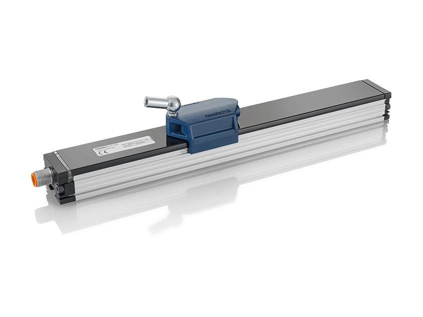
TF1 IO-Link contactless inductive linear transducer
- Manufacturer: Novotechnik
- Category: Displacement, SENSORS, Linear Transducers
Novotechnik TF1 IO-Link inductive transducer. NOVOPAD inductive technology, contactless.
Non-contact linear inductive position transducer with active floating position marker. Stroke from 100 to 1000 mm. Reproducibility up to 5 µm. IP67 protection. Principle: emitter and receiver coils on the same board; the marker induces a current in the receivers, with sine/cosine structures on a thick and a thin track.
Key points
- Unlimited mechanical life (with floating placeholder)
- Output refresh rate: 1 kHz
- Reproducibility: up to 5 µm
- IP67 protection: a GORE membrane equalizes pressure in response to temperature changes
Technical Frequently Asked Questions
What can be connected to the TF1 IO-Link inductive transducer?
It can be connected to Novotechnik M12 connectors and cables and Novotechnik linear sensor positioners (magnets and cursors).
How do I order the TF1 IO-Link inductive transducer?
The order code has 5 fields: stroke (mm), mechanical version, interface, parameters, and connection. For example, TF1-0800-001-A11-107 is the version with an 800 mm electrical range, profile, IO-Link, 5 µm resolution in Balanced mode with position, and a 4-pole M12x1 connector. All the options for each field are available in the order code configurator on this page.
Under what conditions does the TF1 IO-Link inductive transducer operate?
Operating temperature: -40 … +85 °C. Protection: IP67, with GORE membrane pressure equalization, with the connector fixed.
Properties
| Feature | Specification |
|---|---|
| Lengths | |
| Electrical range, level B | 0100 … 1000 mm, in 100 mm increments; other lengths available upon request |
| Housing length, dimension A | level B + 76.5 mm |
| Mass | 220 + 1.1 x B (B in mm) g |
| Description | |
| Housing | Anodized aluminum AlMgSi0.5 F22, 3.3206.71 |
| Inner casing | PA6 GF30 |
| End flanges | Aluminum G AlSi12Cu1 (FE) |
| Status indicator (LED) | PC |
| Mounting | Adjustable flanges (included) or slot nut, e.g. M8 DIN 439 nut |
| Placeholder | Floating, made of plastic; or guided, made of plastic, with angular or axial articulation |
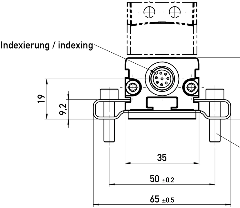
| Electrical connection | M12x1 4-pole shielded connector |
| Electronics | The connector housing is attached to the sensor housing; the housing is capacitively decoupled from the electronics. |
| Others | 2 Multifunction LEDs as an indicator of operating voltage and status |
| Electrical data | |
| Measured variables | Position, speed, and temperature |
| Electrical range (dimension B) | 0100 … 1000 mm |
| Protocol | IO-Link Spec V1.1 according to IEC 61131-9 |
| Profile | Smart Sensor Profile (compatible with V1.0) |
| Configurability | Measured variables (position, speed); product variants of the order specifications (e.g., 1 x position) can also be configured by the customer (e.g., to 1 x position and 1 x speed) |
| Programmable parameters | Zero point shift, resolution, averaging |
| Transfer speed | COM 3 (230.4 kB) |
| Type of plot | 2,2 |
| Minimum cycle time | 1 ms |
| Update frequency (output) | 1 kHz |
| Position resolution | 1 or 5 µm |
| Speed resolution | 0.1 or 0.5 mm/s |
| Reproducibility, High precision mode, dimension B ≤ 400 mm | < 5 µm |
| Reproducibility, High precision mode, dimension B > 400 mm | < 8 µm |
| Reproducibility, Balanced mode, dimension B ≤ 400 mm | < 10 µm |
| Reproducibility, Balanced mode, dimension B > 400 mm | < 15 µm |
| Signal propagation delay, High precision mode | 4 ms |
| Signal propagation delay, Balanced mode | 1 ms |
| Hysteresis, High Prec mode | ≤ 5 µm |
| Hysteresis, Balanced mode | ≤ 10 µm |
| Absolute linearity | ≤ ±100 µm |
| Electrical zero point tolerance | ±1 mm |
| Temperature coefficient (temperature error) | ≤ 15 ppm/K (min. 0.01 mm/K) |
| Supply voltage | 24 (18 … 32) VDC |
| Power supply voltage ripple | max. 10 % Vss |
| No-load consumption | 2.4 W |
| Overvoltage protection | 36 VDC (permanent) |
| Reverse polarity protection | Yes, up to the maximum supply voltage. |
| Short circuit protection | Yes (output to GND and max. supply voltage) |
| Insulation resistance (500 VDC) | ≥ 10 MΩ |
| Signal with broken cable | No communication |
| Environmental conditions | |
| Maximum operating speed with valid output signal | 10 m/s |
| Maximum operating acceleration with valid output signal | 200 m/s² |
| IEC 60068-2-27 Shock | 100 g (11 ms), one stroke |
| Vibration IEC 60068-2-6 | 20 g (5 … 2000 Hz, Amax = 0.75 mm) |
| DIN EN 60529 protection | IP67, with GORE membrane pressure equalization, with the connector fixed |
| Life | Mechanically unlimited (with floating placeholder) |
| Working temperature | -40 … +85 °C |
| Storage temperature | -40 … +85 °C |
| Working humidity | 0 … 95 % HR (non-condensing) |
| MTTF (IEC 60050) | 196 years |
| Accordance | EC |
| Electromagnetic compatibility | |
| EN 61000-4-2 | Electrostatic discharges (ESD) 4 kV, 8 kV |
| EN 61000-4-3 | Electromagnetic fields 10 V/m |
| EN 61000-4-4 | Fast transients (burst) 1 kV |
| EN 61000-4-6 | Conducted disturbances induced by RF fields 10 V rms. |
| EN 55016-2-3 | Radiated disturbances, class B |
| IO-Link process and event data | |
| Process data | Signed integer value: 32-bit position (4 bytes), or 32-bit position and 16-bit speed (6 bytes) |
| Device ID | 002100 (0x000834) position; 002110 (0x00083E) position and speed |
| Error value | 0x7FFFFFFC, with the data marked as invalid, if the placeholder is not detected |
| Averaged | 0: no moving average; 1 … 5: moving average over 2, 4, 8, 16 or 32 values |
| Events | Warning 0x8C10 / 0x8C30: marker outside the defined working range (below / above); error 0x8C20: marker missing; 0x4210: internal overtemperature; 0x5000: internal system failure; 0x8CA0: storage failure |
| Option | Meaning |
|---|---|
| Example: TF1-0800-001-A11-107 = 800 mm electrical range, profile, IO-Link, 5 µm resolution in Balanced mode with position and 4-pole M12x1 connector. | |
| 1. Electrical range (mm) | |
| 0100 … 1000 | Standard, 100 mm steps; others, on request |
| 2 · Mechanical version | |
| 001 | Profile |
| 3 · Electrical interface | |
| TO | IO-Link |
| 4 · Interface parameters (A__) | |
| 11 | Resolution 5 µm, Balanced mode, position |
| 12 | 5 µm resolution, Balanced mode, position and velocity |
| 31 | Resolution 1 µm, High precision mode, position |
| 32 | 1 µm resolution, High precision mode, position and speed |
| 5 · Electrical connection | |
| 107 | M12x1 connector, 4 poles |
| The code is formed using one option from each field, in the order shown in the example. Contact us and we will confirm the exact reference. | |
Related documentation, cases, and guides
Technical documentation
- Novotechnik General Catalogue: Linear and Angular Position Sensors
- Technical definitions of potentiometers: linearity, RGV and hysteresis
- Novotechnik position sensors with IO-Link interface
- Position sensors for valves and actuators: Novotechnik series
- Novotechnik linear and rotary sensors for automotive applications
Other products