Schreiber SM40 LVDT Sensor – Amplified Linear Displacement Ø25 mm
- Manufacturer: Schreiber Messtechnik
- Category: Displacement, Amplified LVDTs, SENSORS, LVDT Sensors
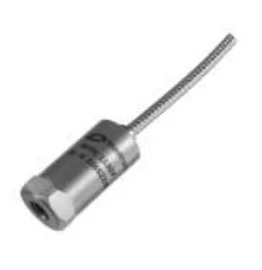
The Schreiber SM40 is an inductive linear displacement LVDT sensor with integrated electronics. Nominal strokes: 20, 40, 70, 100, 150, and 200 mm. It features a cylindrical housing, 25 mm in diameter, made of stainless steel. Applications include measuring travel, movement, and position in industrial machinery, automation, test benches, and control systems.
The movable core is made of nickel-iron (Ni-Fe) alloy. Its position modifies the inductance distribution in the transducer coils. The internal electronics convert this variation into a signal proportional to the displacement: 0–20 mA, 4–20 mA, 0–10 VDC, or ±10 VDC, depending on the model.
Models SM401, SM402, SM403, SM404, SM405, SM406, SM407, and SM408, with increasing or decreasing outputs. Linearity classes: 0.5% and 0.25%. Mechanical configurations: moving core, guided rod, spring-loaded probe, ball joints, and cable output.
The integrated electronics allow the SM40 to be connected to compatible analog inputs of PLCs, data acquisition systems, indicators, and control equipment, without external LVDT conditioning.
Models, references and characteristics of the Schreiber SM40
1. Models SM401 to SM408: 4–20 mA, 0–10 V and ±10 V outputs
The SM40 series has eight electrical models that allow you to select the output signal and its direction of variation.
| Model | Sign | Feeding | Sense | Central value |
|---|---|---|---|---|
| SM401 | 0–20 mA | 20–32 VDC | Growing | 10 mA |
| SM402 | 0–20 mA | 20–32 VDC | Decreasing | 10 mA |
| SM403 | 4–20 mA | 20–32 VDC | Growing | 12 mA |
| SM404 | 4–20 mA | 20–32 VDC | Decreasing | 12 mA |
| SM405 | ±10 VDC | ±13…±16 VDC | Growing | 0 V |
| SM406 | ±10 VDC | ±13…±16 VDC | Decreasing | 0 V |
| SM407 | 0–10 VDC | 20–32 VDC | Growing | 5 V |
| SM408 | 0–10 VDC | 20–32 VDC | Decreasing | 5 V |
In increasing models, the signal increases as the rod moves toward the sensor connector. In decreasing models, this relationship is reversed.
Models with current output and 0–10 V use a 20–32 VDC power supply. References SM405 and SM406 require a symmetrical power supply of ±13 to ±16 VDC.
2. Strokes and dimensions: LVDT sensors from 20 to 200 mm
Six standard measurement strokes. Housing diameter: Ø25 ±0.1 mm. Longitudinal dimensions and weights vary with stroke.
| Career | L1 | L2 body | Body weight | Rod weight |
|---|---|---|---|---|
| 20 mm | 40 mm | 110 mm | 210 g | 15 g |
| 40 mm | 50 mm | 140 mm | 240 g | 19 g |
| 70 mm | 65 mm | 200 mm | 310 g | 25 g |
| 100 mm | 80 mm | 250 mm | 380 g | 31 g |
| 150 mm | 105 mm | 350 mm | 520 g | 41 g |
| 200 mm | 130 mm | 500 mm | 720 g | 56 g |
L1 corresponds to the protruding length of the rod in the central position. L2 identifies the length of the body, according to the Schreiber plane.
The assembly plan incorporates a Ø5 mm rod, M5×15 threaded end and rear fixings indicated in the technical drawing.
The SM42 series, with integrated electronics and a Ø25 mm body, covers standard displacements of 80, 170, 240 and 360 mm.
3. SM40 order references and linearity classes
The order reference identifies the electrical output, nominal stroke, linearity class, and mechanical options.
Reference structure: SM40X.STROKE.PRECISION.OPTION
- SM401–SM408: Electrical output selection and signal direction.
- Stroke: 20, 40, 70, 100, 150 or 200 mm.
- .1: linearity 0.25%.
- .2: linearity 0.5%.
- .T: probe with spring return, for strokes up to 100 mm.
- .F: guided rod with stops.
- .G / .H: joint joints.
- .K: output via cable.
- .R: protective cover.
Manufacturer's documented reference: SM403.40.2.T. Corresponds to a sensor from the SM40 series with 4–20 mA scaling output, nominal travel of 40 mm, linearity class 0.5% and probe execution.
Special options and code combinations are confirmed with the manufacturer.
Accuracy and quality control: The Schreiber SM40 series offers linearity classes of ±0.25% and ±0.50% of the nominal travel, depending on the selected reference. Schreiber Messtechnik performs individual linearity checks using records and deviation curves throughout the measuring stroke. The manufacturer has a quality management system certified according to DIN EN ISO 9001:2015. Linearity is not equivalent to resolution or total measurement uncertainty.
4. Mechanical configurations: free rod, probe, guide and ball joints
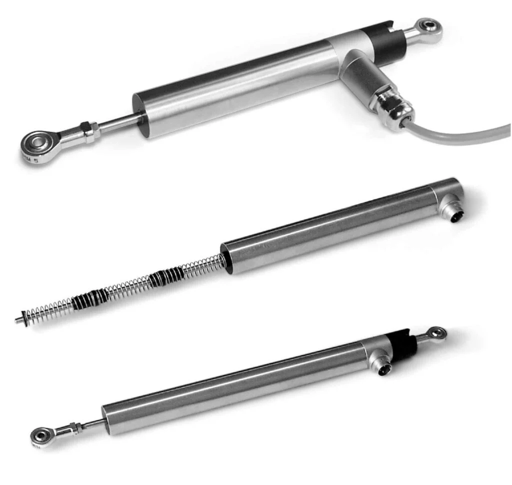
Mechanical constructions of the SM40:
- SM40 standard: core and movable rod for coupling to the mechanism to be measured.
- Version .D: rod guide in Delrin.
- Version .F: guided rod with stops.
- Version .T: probe with return spring, documented for strokes of 20, 40, 70 and 100 mm.
- Version .G: ball joint on the rod.
- Version .H: ball joint in the housing.
- Version .FGH: construction with guided rod and articulation ball joints.
- Version .R: protective cover for environments with abundant dirt.
- Version .K: cable exit via cable gland.
The construction with two ball joints allows the assembly to be adapted to articulated mechanisms.
5. Schreiber SM40.T probe: stroke and spring force
The SM40.T versions use a spring-loaded probe to measure displacements by direct contact with a moving part or surface. The manufacturer documents the following variants:
| Career | BM | B1 | L2 | Central force | Constant |
|---|---|---|---|---|---|
| 20 mm | 70 mm | 85 mm | 110 mm | ≈4 N | 0.07 N/mm |
| 40 mm | 70 mm | 98 mm | 140 mm | ≈4 N | 0.07 N/mm |
| 70 mm | 110 mm | 160 mm | 200 mm | ≈4 N | 0.05 N/mm |
| 100 mm | 140 mm | 195 mm | 250 mm | ≈4 N | 0.03 N/mm |
BM represents the rod in the central position, B1 the maximum extension, and L2 the body length. The indicated force is approximate and corresponds to the central position of the probe.
6. PLC connection: cabling, power supply and permissible loads
The SM401–SM404 references provide current signals of 0–20 or 4–20 mA, with load resistance of 0 to 500 Ω and maximum consumption of 60 mA.
The SM405–SM408 versions provide ±10 V or 0–10 V voltage signals for loads of at least 2 kΩ. The UK datasheet specifies a maximum current draw of 50 mA for these outputs.
Three-contact connection: SM401–SM404 and SM407–SM408:
- Pin 1: +UB.
- Pin 2: −UB / 0 V.
- Pin 3: current or voltage output.
Four-contact connection: SM405 and SM406:
- Pin 1: +UB.
- Pin 2: 0 V.
- Pin 3: −UB.
- Pin 4: voltage output.
For wired versions, the plug identifies the colors red (+UB), black (−UB), brown (output) and orange (0 V for symmetrical power supply versions).
Before connecting the transducer, the type of analog input, power supply, and electrical diagram of the corresponding variant must be verified.
7. IP66 protection, wired versions and environmental conditions
The official English data sheet for the Schreiber SM40 specifies IP66 for the system with the appropriate and correctly mounted auxiliary connector.
The Spanish documentation also includes a .Kx version with cable glands and oil-resistant cable, described as having IP67 protection. The protection level should be associated with the connection configuration actually supplied.
The documented environmental and dynamic characteristics include:
- Temperature: −20 to +85 °C according to standard English data sheet.
- Thermal drift: less than 0.01%/°C.
- Limiting frequency: 800 Hz.
- Vibrations: 20 g RMS, with peaks of 50 g.
- Shocks: 250 g SRS, 20–2000 Hz.
Special versions are available for temperatures up to +100 °C with Kynar AWG20 cable output, subject to configuration confirmation.
8. Mounting accessories, connectors and mechanical protection
Schreiber offers specific accessories for mounting SM40 sensors of Ø25 mm:
- SM906.400: Nickel-plated brass fixing clamp, with M4×35 screws.
- SM906.401: Polypropylene clamp, with M6×35 screws.
- SM901.400: complementary connector described in the Spanish documentation with IP40 protection.
- SM901.402: Complementary connector described with IP65 protection.
- SM40.R: Protective cover for very dirty environments, in compatible races.
- SM40.FGH: articulated configuration with guided rod and ball joints.
The manufacturer also specifies a connector suitable for achieving IP66 in the standard configuration. The specific connector part number should be verified before delivery, especially when replacing existing installations.
9. Applications and selection between Schreiber SM30, SM40 and SM42
SM40 applications: linear displacement, position and stroke in machinery, actuators, industrial mechanisms and test benches.
- Stroke control in linear actuators.
- Measurement of displacement of mechanical elements.
- Monitoring the position of industrial mechanisms and equipment.
- Measurement on test benches and verification devices.
- Motion tracking with ball joint mounting.
- Integration of analog signals in PLCs and acquisition systems.
- Dimensional measurement using a spring-loaded probe.
For shorter travel and M30×1.5 threaded mounting, the Schreiber SM30 series It offers strokes of 5, 10 and 15 mm.
For higher nominal strokes, up to 360 mm, Schreiber offers the SM42 series. The choice between SM40 and SM42 depends on the required stroke, body dimensions, and mounting options.
See also: amplified LVDT sensor category and Schreiber Messtechnik range.
Frequently asked questions about the Schreiber SM40 LVDT sensor
What races does the Schreiber SM40 have?
The SM40 is available in nominal strokes of 20, 40, 70, 100, 150, and 200 mm. For strokes up to 360 mm, there is the Schreiber SM42 series.
What is the accuracy and linearity of the Schreiber SM40 sensor?
The Schreiber SM40 sensor is available in linearity classes of ±0.25% and ±0.50% of the nominal travel, depending on the variant selected. Over a 20 mm stroke, 0.25% equates to a 0.05 mm deviation from linearity. This should not be confused with the resolution or the total uncertainty of the measuring system.
Which SM40 model provides 4–20 mA output?
The SM403 and SM404 models provide a 4–20 mA signal. The SM403 has a rising signal and the SM404 a falling signal, with a 20–32 VDC power supply.
Which Schreiber SM40 models offer 0–10 V output?
The SM407 and SM408 models offer a 0–10 VDC output with a 20–32 VDC power supply. The signal is rising in the SM407 and falling in the SM408.
Does the Schreiber SM40 sensor incorporate electronics?
Yes. The SM40 integrates the conditioning electronics and directly provides an analog signal proportional to the displacement, without an external LVDT amplifier.
Is there an SM40 with a probe and spring return?
Yes. The SM40.T version is documented for strokes of 20, 40, 70 and 100 mm, with an approximate force of 4 N in the center position.
What does the reference SM403.40.2.T mean?
Identify an SM40 sensor with 4–20 mA scaling output, 40 mm nominal stroke, 0.5% accuracy class, and probe execution.
Can an SM40 be connected directly to a PLC?
Yes, when the PLC has an analog input compatible with the selected signal. The sensor's power supply, load capacity, and wiring should also be checked.
Where can I buy Schreiber SM40 LVDT sensors in Spain?
Guemisa distributes Schreiber Messtechnik sensors in Spain. SM40: strokes from 20 to 200 mm.
Schreiber SM40 Documentation
Documentation: Schreiber SM40/SM42 technical specifications in Spanish and Official Schreiber SM40 specifications in English.
Guemisa – Sensors and Instrumentation. LVDT sensors and Schreiber inductive displacement transducers.
Properties
| Specification | Schreiber SM40 / SM401–SM408 |
|---|---|
| Manufacturer | Schreiber Meßtechnik GmbH, Germany |
| Sensor type | LVDT sensor / amplified linear inductive transducer |
| Technology | Differential inductive, Ni-Fe moving core |
| Conditioning electronics | Integrated into the sensor |
| Series | SM40 |
| Electric models | SM401 / SM402 / SM403 / SM404 / SM405 / SM406 / SM407 / SM408 |
| SM40 nominal strokes | 20 / 40 / 70 / 100 / 150 / 200mm |
| Related family SM42 | 80 / 170 / 240 / 360 mm |
| Standard linearity | <0.5 % |
| Linearity option | 0.25 % according to reference |
| Linearity code .1 | 0,25 % |
| Linearity code .2 | 0,5 % |
| Housing diameter | Ø25 ±0.1 mm |
| Standard rod diameter | Ø5 mm |
| Threaded end | M5×15 |
| Body length L2 | 110 / 140 / 200 / 250 / 350 / 500 mm, depending on the stroke |
| Central L1 projecting length | 40 / 50 / 65 / 80 / 105 / 130 mm, depending on the stroke |
| Body weight | Approx. 210–720 g depending on model |
| Rod weight | Approx. 15–56 g depending on model |
| SM401 / SM402 Output | 0–20 mA, increasing / decreasing |
| SM403 / SM404 Output | 4–20 mA, increasing / decreasing |
| SM405 / SM406 Output | ±10 VDC, increasing / decreasing |
| SM407 / SM408 Output | 0–10 VDC, increasing / decreasing |
| SM401–SM404 Power Supply | 20–32 VDC |
| SM405-SM406 Power Supply | Symmetrical ±13…±16 VDC |
| SM407–SM408 Power Supply | 20–32 VDC |
| Central value 0–20 mA | 10 mA |
| Central value 4–20 mA | 12 mA |
| Center value ±10 V | 0 V |
| Center value 0–10 V | 5 V |
| Current output load | 0–500 Ω |
| Voltage output load | ≥2 kΩ |
| Power consumption, current output | Maximum 60 mA |
| Power consumption, voltage output | Maximum 50 mA, English connector |
| Rippled current output | <0.005 mA peak-to-peak |
| Rippled voltage output | <5 mV peak-to-peak |
| Residual voltage SM407 / SM408 | Maximum 0.1 VDC |
| Load dependency, current output | <0.001 % for ΔRL = 100 Ω |
| Feeding dependency | <0.05 % for ΔUB = 1 V |
| frequency limit | 800 Hz |
| Thermal drift | <0.01 %/°C |
| Standard temperature, English data sheet | -20…+85 °C |
| Special temperature | Up to +100 °C with Kynar AWG20 cable, subject to availability |
| Standard protection | IP66 with suitable complementary connector mounted |
| Cable version protection .Kx | IP67 according to Spanish data sheet |
| Shock resistance | 250 g SRS, 20–2000 Hz |
| Vibration resistance | 20 g RMS, peaks of 50 g |
| Body material | Stainless steel |
| Rod material | Stainless steel |
| Core material | Ni-Fe Alloy |
| Connector housing | Nickel-plated brass |
| Electrical contacts | Gold-plated brass |
| probe dock | Stainless steel |
| Probe .T | 20 / 40 / 70 / 100 mm, center force approx. 4 N |
| Other buildings | .D / .F / .G / .H / .K / .R according to execution |
| Metal clamp | Schreiber SM906.400, nickel-plated brass |
| Plastic clamp | Schreiber SM906.401, polypropylene |
| Linearity verification | Individual control of linearity deviation during sensor travel, documented by Schreiber inspection records |
| Manufacturer's quality management system | Certified according to DIN EN ISO 9001:2015 |

Related documentation, cases, and guides
Other products