
Catalogue · NCTE
Operating principle
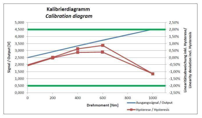
The technology is magnetoelastic and measures without contact, even in extreme environmental conditions. The metal shaft is directly magnetized. When the torque distorts the shaft, its magnetic field is distorted accordingly (inverse magnetostrictive principle). These changes are detected and measured without direct physical contact with the shaft, and an output signal is generated showing the torque, rotation, and direction.
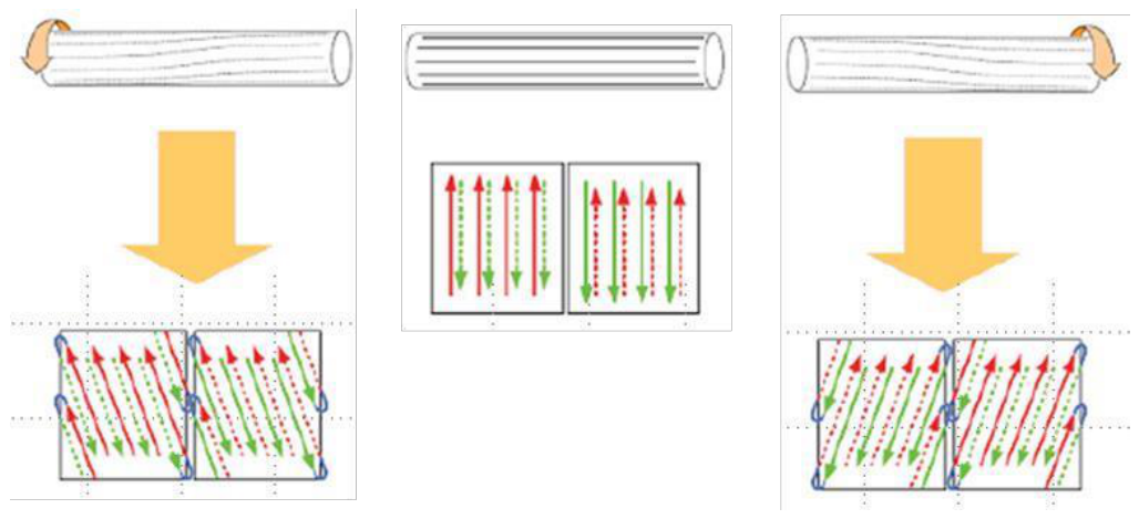
If space is limited, the machine shaft can become part of the sensor, depending on the material (DIN 1.2767, 1.5752, 1.4021, 300M).
5-step sensor manufacturing
| Passed | Operation |
|---|---|
| 1 | Ultrasonic cleaning and demagnetization of the shaft |
| 2 | Generation of the magnetic field on the axis |
| 3 | Electronics assembly, including coil integration |
| 4 | Sensor calibration |
| 5 | Ultimate casing |
Comparison with strain gauges and optical sensors
In NCTE technology, the shaft itself becomes the primary sensor, and a magnetic field is used instead of an additional component on the shaft. The document states that it is maintenance-free and remains stable over time even when not in use, is easy to integrate, and offers weight savings.
| Feature | Strain gauge | Reverse magnetostriction |
|---|---|---|
| Robustness (thermal, mechanical, chemical) | Limited | Very high |
| Useful life (thermal, mechanical, chemical) | Limited | Very high |
| Quick response to torque change | Half | Very high |
| Electromagnetic susceptibility | Limited | Limited |
| Variety of axle materials | High | Limited |
| Accuracy | Very high | High |
| Technology | Limitations cited |
|---|---|
| Optical sensors | Sensitive to dirt, dust, steam, and humidity; limited stability over time |
| Strain gauge sensors | Sensitivity to temperature and chemical agents, external forces and vibrations; mechanical hysteresis; installation and maintenance, even if not in use |
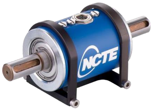
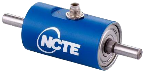
Standard series: technical data
| Series | Measurement range (Nm) | Precision | Rotation speed | Exit signals | Output frequency |
|---|---|---|---|---|---|
| 2000 | 2,5; 5; 7,5; 15; 17,5; 60; 75; 140; 175; 250; 400; 500 | ≤ ±1 % | ≤ 5000 rpm | 0-5 V | 1000 Hz |
| 2300 | 0.5; 1; 2.5; 5; 10; 20; 50; 100 (bidirectional) | ≤ ±0.5 % | ≤ 10,000 rpm | 0-5 V / 4-20 mA / CAN-Bus / USB | 1000 Hz |
| 3000 | Round axle: 50; 100; 250; 500; 1000; 2000. Square axle: 50; 250; 1000 (bidirectional) | ≤ ±0.2% | ≤ 10,000 rpm | 0-10 V / 4-20 mA | 2500 Hz |
| 4000 | Round axle: 50; 100; 250; 1000. Square axle: 50; 250; 1000 (bidirectional) | ≤ ±0.1 % | ≤ 10,000 rpm | 0-10 V / 4-20 mA | 2500 Hz |
| 5000 | 10,000; 15,000 (bidirectional); customer-specific calibration > 15,000 Nm on request | ≤ ±0.5 % | ≤ 2500 rpm | 0-10 V / 4-20 mA | 2500 Hz |
| 7000 | 3000; 5000 (bidirectional) | ≤ ±0.5 % | ≤ 3500 rpm | 0-10 V / 4-20 mA / CAN-Bus / USB | 2500 Hz |
| 7300 | 3000 (bidirectional) | ≤ ±0.5 % | ≤ 1100 rpm | 0-10 V / 4-20 mA / CAN-Bus / USB | 2500 Hz |
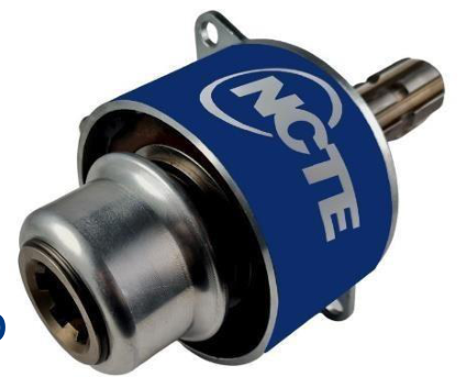
Use cases by series
| Series | Use cases |
|---|---|
| 2000 | Torque wrenches, poultry feeders, industrial uses |
| 2300 | Fine manufacturing, friction torque measurement, end-of-line testing |
| 3000 | Electric motors, end-of-line testing, motorsports |
| 4000 | End-of-line testing, laboratories, motorsport |
| 5000 | Drilling wells, valves, cranes |
| 7000 | External machinery with power take-off shaft, pumps, valves, operation and testing |
| 7300 | Overload protection, power distribution, stability testing, harvesters, balers, rotary harrows, trucks, mining, pumps |
7300 Series for power take-off shaft
- Designed for harsh agricultural environments, IP65.
- Small and lightweight.
- Connectable directly to the power take-off (PTO) shaft, without additional bushings or flanges.
- Analog and digital output signals: volts, mA, USB and CAN.
- Connects directly to a PC via USB; cable included.
- Its compact design reduces vibration on the shaft and takes up minimal additional space in the machine.
- No downtime for sensor maintenance during the planting and harvesting season.
Frequently Asked Questions
How does an NCTE sensor measure torque?
The metal shaft is magnetized. The torque distorts the shaft and its magnetic field changes (reverse magnetostrictive principle); this change is measured without contact and generates a signal that shows the torque, rotation, and direction.
What torque range do the standard series cover?
From 0.5 Nm (2300 series) up to 10,000 and 15,000 Nm (5000 series), with customer-specific calibration above 15,000 Nm available upon request.
Which series has the highest accuracy?
The 4000 series, with accuracy ≤ ±0.1% and ranges from 50 to 1000 Nm.
What exit signals do they offer?
According to the series: 0-5 V, 0-10 V, 4-20 mA, CAN-Bus and USB.
What level of protection does the 7300 series have?
IP65, designed for harsh agricultural environments, with a rotation speed ≤ 1100 rpm and a range of 3000 Nm.
What are the steps involved in manufacturing the sensor?
Ultrasonic cleaning and demagnetization of the shaft, generation of the magnetic field, assembly of the electronics with the coil, calibration and final casing.
Related
- NCTE Torque Sensors
- Torque sensor
- NCTE Magnetostrictive Torque Sensor
- NCTE 7300 technical specifications: torque at power take-off
- NCTE 4000 Series Torque Sensor
- All technical information about GUEMISA
Below, the original PDF document is available for viewing or downloading.