Technical tutorial · NCTE
Measurement principle: reverse magnetostriction
NCTE's contactless torque sensors are based on reverse magnetostriction: the magnetic field of an object changes due to mechanical forces. In a magnetized object, the mechanical load distorts the crystal lattice and modifies the magnetization; measuring this change yields the torque or force.
Magnetization is introduced using a patented process. The magnetic field is circular and always returns to its original orientation after deformation or vibration. A non-contact receiver detects changes in the field and evaluates them at a distance of several millimeters, even through dirt or lubricant and at high speeds.
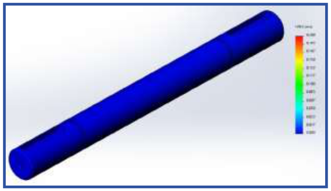
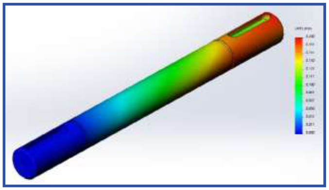
In comparison, conventional torque sensors based on strain gauges are still suitable for very precise measurements on test benches, but their acquisition and maintenance are expensive, which prevents their use in large volumes of serial production.
Sensor construction
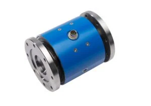
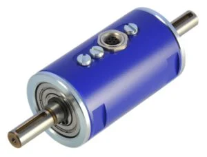
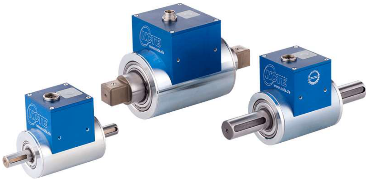
A non-contact torque and force sensor consists of an existing magnetized shaft (primary sensor) and a readout unit (secondary sensor) configurable according to the application. The shaft could be, for example, that of an extruder, a steering wheel, or a car transmission.
| Passed | Operation |
|---|---|
| 1 | Ultrasonic cleaning and demagnetization of the shaft |
| 2 | Unique introduction of magnetic fields (Pulse Current Magnetic Encoding) |
| 3 | Electronics configuration, including coil placement |
| 4 | Sensor calibration |
| 5 | Construction with casing |
| Fact | Worth |
|---|---|
| Magnetization pulse current | A few kiloamperes, depending on the shaft diameter |
| Pulse duration | A few milliseconds |
| Low field variation pair | Between 150 μT and 200 μT |
| Reading distance | Several millimeters, no contact |
| Calibration | Just a few seconds |
| Reader assembly housing | Non-magnetic |
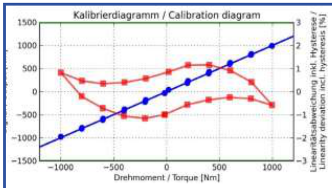
Primary sensor material
The decisive factor for a steel to serve as a primary sensor is not its remanence or permeability, but its magnetostrictive properties. The harder the steel, the more suitable it is: it is more magnetic and exhibits less torsion, with less hysteresis after charging and discharging. Magnetic properties also depend on the material's thermal and mechanical history, so each material is examined and tested beforehand.
| Steels cited as suitable |
|---|
| 45NiCrMo16 (1.2767) |
| 15NiCr13 (1.5752) |
| X20Cr13 (1.5032) |
| S155/300M |
Features and advantages of the contactless principle
| Feature | Fact |
|---|---|
| Standard precision | 0.1% to 2%, adjustable according to application |
| Accuracy of standard sensors | Less than 0.1% |
| Nominal torques of standard sensors | 1 to 25,000 Nm |
| Speed (standard sensors) | Above 10,000 rpm |
| Speed with externally mounted electronics | Above 40,000 rpm |
| Temperature | Up to 125 °C, with continuous temperature load and externally mounted electronics |
| Sampling frequency in robotics | Greater than 10 kHz |
| Influence of oil and water | They do not affect operations |
| Maintenance | It is not required; overloading poses no risk to the sensors. |
- The existing shaft becomes the primary sensor and the secondary sensor is designed individually.
- The measurement is performed without contact, without cables or wear.
- The patented magnetic encoding is stable over time.
- The original design of the axle does not need to be modified.
- Secondary sensors save space and can be used in hollow shafts.
- The technology is useful both in test benches and in serial applications.
The principle allows for the measurement of pressure and tension, torque and speed, and deflection (static or dynamic), and can be combined with standard speed measurement techniques or active temperature compensation.
Applications
The fields of use cited are automotive, Industry 4.0, mechanical engineering, electric bicycles, motorsports, medical technology and off-highway.
Collaborative robots
The torque-carrying shafts at each joint of the robotic arm are magnetized. By measuring on hollow shafts, these can also guide control cables and pneumatics without altering the original design. The secondary sensors are extremely compact and detect force changes at sampling frequencies above 10 kHz. They can combine torque and deflection measurements on two axes in a single sensor.
Active steering in automotive
In active steering, the existing steering shaft is magnetized, and a contactless sensor measures the torque the driver applies to the steering wheel. The electronic control unit then calculates the required assistance from the electric motor. Magnetizing the existing shaft preserves the original design and adds no weight to the steering system.
Range and durability testing
| Essay or fact | Result |
|---|---|
| Load changes | More than 2 million |
| Temperature cycles | 68 |
| Vibration | 120 hours |
| Unilateral exposure | 8 weeks, with no significant distortion of the measurement by hysteresis (<1%) |
| Optional homologation | 2000 Series: ATEX Zone II 3G |

In addition to standard sensors, NCTE develops customized sensor solutions for each application, from the initial idea and first prototype to production, both on-demand and in series.
Frequently Asked Questions
On what principle are NCTE torque sensors based?
In reverse magnetostriction: the magnetic field of a magnetized shaft changes due to mechanical forces, and a non-contact reading unit measures that change.
How accurate are they?
Standard accuracy ranges from 0.1% to 2%, adjustable depending on the application. Standard sensors achieve accuracies of less than 0.1%.
What torque range do standard sensors cover?
Nominal torques from 1 to 25,000 Nm, with speeds exceeding 10,000 rpm.
Which steels serve as a primary sensor?
The harder the steel, the more suitable it is. Examples include 45NiCrMo16 (1.2767), 15NiCr13 (1.5752), X20Cr13 (1.5032), and S155/300M.
Is there an ATEX-approved version?
Yes, as an option for the 2000 series non-contact torque sensors, with ATEX Zone II 3G approval.
Related
- NCTE Torque Sensors
- Torque sensor
- NCTE Torque Sensor Catalog
- Measuring torque on NCTE motor test benches
- NCTE 2000 and 2200 Series Torque Transducer – 500 Nm | 5,000 RPM
- All technical information about GUEMISA
Below, the original PDF document is available for viewing or downloading.