
Technical guide · GUEMISA
A linear potentiometer is a voltage divider: it is supplied with a stable voltage, for example 10 V, and the wiper delivers a fraction of that voltage proportional to its position. It can be connected directly to a 0–10 V analog input of the PLC, provided the input has very high impedance, because potentiometer transducer connectors recommend a wiper current of 1 µA maximum. If the cable is long, the environment is noisy, or the PLC only provides 4–20 mA, a signal conditioner (MUW, MUK, or MUP) is inserted to supply power to the potentiometer and deliver the standardized signal.
The potentiometer as a voltage divider
A linear potentiometric transducer has three connections: the two ends of the track and the wiper. The voltage Ub is applied between the ends; the wiper, which moves with the stem, outputs a voltage Us between 0 and Ub. The ratio Us/Ub represents the relative position along the track. With 10 V and 40% of the track traveled, the wiper outputs 4 V.
This signal is ratiometric in nature: it depends on the ratio between Us and Ub, not on the absolute resistance value (LWH: tolerance ±20%, and temperature coefficient of the output/applied voltage ratio of typ. 5 ppm/K). The nominal resistance matters little for accuracy and much for current draw and cursor load.
Direct connection to a 0…10 V input
A stable 10V power supply feeds the trace, the cursor goes to the analog input, and the power supply ground is connected to the input reference. Three points need to be taken care of.
- Stable power supply. The signal is proportional to Ub. Supplying the track with 24 V would result in up to 24 V at the cursor, exceeding the input range, and any fluctuations in the power supply would be passed on to the reading. A stable 10 V reference is required, or a power supply whose value is also measurable (see «Ratiometric Output»). The connectors set the maximum Ub to 42 VDC.
- Cursor current. LWH, TLH, T/TS, LWG and TEX indicate a recommended cursor current of ≤ 1 µA (in TEX, < 1 µA) and a maximum current of 10 mA in case of failure. The cursor should go to an input that draws almost no current.
- Input impedance. With 10 V at the cursor, a current of 1 µA corresponds to a load resistance of 10 MΩ. Many 0–10 V modules have lower impedances: check the datasheet.
How much error does the cursor loading introduce?
An input with resistor Rin forms a divider with the portion of the track between the cursor and ground. The maximum error, at mid-travel, is approximately 0.25 × R / Rin, where R is the total resistance of the track. With a 5 kΩ potentiometer:
| Input impedance | Current in the cursor at 10 V | Mid-race error |
|---|---|---|
| 100 kΩ | 100 µA | Approx. 1.25% of the range |
| 1 MΩ | 10 µA | Approx. 0.125% of the range |
| 10 MΩ | 1 µA | Approx. 0.0125% of the range |
The LWH-0300 (300 mm, 5 kΩ) has an independent linearity of ±0.06%: a 100 kΩ input would add an error twenty times greater, and with 10 MΩ the load error remains below linearity. These are indicative calculations.
Ratiometric output: when it matters
«Ratiometric» means that the output is a fraction of the supply voltage and varies with it. This is an advantage if the analog-to-digital converter uses that same voltage as a reference, because the variations cancel each other out in the reading; and a disadvantage if the measurement is taken with a fixed reference and the supply voltage fluctuates.
- The IPX-7900 rotary potentiometer declares a ratiometric output at Ub (Ub max. 42 V). The TFD-4000 Hall sensor gives 0.25–4.75 V with 5 VDC, also ratiometric: the power supply must be stable.
When to use a conditioner for 4…20 mA
The conditioner supplies the potentiometer with a very stable internal reference voltage (10 VDC in the MUP-080, MUP-100/150, MUP-110/160, and MUK-350) and takes the cursor signal with a high-resistance input stage (>10 MΩ in the MUP-100/150, MUP-110/160, MUK-350, and MUW), keeping the cursor current within 1 µA. The MUP-410 supplies the potentiometer with 2.5 VDC / 5 mA. It then generates a standardized output. Recommended for use when:
- The PLC only has current inputs or its voltage input is not high impedance.
- The cable is long or passes close to drives and motors: the current suffers less from induced noise and voltage drop.
- Cable break detection is required: in the 4…20 mA range, zero is at 4 mA, so 0 mA indicates a fault. The MUP-410 outputs approximately 3.2 mA if the sensor wire breaks.
- Galvanic isolation is required (MUP-150, MUP-160, MUP-410).
The maximum load of the current output is 500 Ω in MUP-080, MUP-100/150, MUP-110/160 and MUW (< 500 Ω / 12 V on MUP-410): PLC input and wiring must not exceed it.
Comparative table of the three solutions
| Feature | Direct to 0…10 V | With conditioner at 0…10 V | With conditioner at 4…20 mA |
|---|---|---|---|
| Signal on the cable | Cursor tension | Standardized voltage | standardized current |
| Sensor power supply | Stable external source | The conditioner gives it to you. | The conditioner gives it to you. |
| Load on cursor | It depends on the PLC input (≤ 1 µA recommended) | No load (input > 10 MΩ) | No load (input > 10 MΩ) |
| Sensitivity to noise and long cable | High | Average | Low |
| Thread breakage detection | No | No | Yes (0 mA or below 4 mA) |
Which conditioner to choose
| Model | Assembly and protection | Departures | Galvanic isolation |
|---|---|---|---|
| MUP-080 | DIN rail, IP20 | 0…10 V or 4…20 mA (depending on the reference) | No |
| MUP-100 / 150 | DIN rail, IP50 (IP00 terminals) | 0…10 V, ±10 V, 0/4…20 mA, ±20 mA | MUP-150 |
| MUP-110 / 160 | DIN rail, IP50 (IP00 terminals) | 0…10 V, 0…20 mA or 4…20 mA | MUP-160 |
| MUP-410 | DIN rail, IP20 | 4…20 mA (default), 0…20 mA and others; 0…10 V, ±10 V and others | Yeah |
| MUK-350 | Aluminum enclosure, IP66 | 0…10 V, ±10 V, 0…20 mA or 4…20 mA | Not indicated in the data sheet |
| MUW-200 / 250 | DIN 43650 connector box, IP65; LWH and TLH only | 0…10 V, 0…20 mA or 4…20 mA | Not indicated in the data sheet |
The MUW goes in the LWH or TLH connector itself; the MUK-350 solves the same problem in the field for any potentiometer; the MUPs go in the panel.
Shielded and mass
- Shielded and braided cable. In-box conditioners recommend 3 braided wires with mesh (MUK-350: 0.25 mm², Ø 4.5…6.5 mm; MUW: 3 or 4 wires, Ø 4…10 mm). The MUK-350 fitting has an EMC-compliant shielded contact.
- LWH: Protective grounding shield on the customer side; on the sensor, terminated near the housing without being connected to it or to the connector contacts. Pin 4 only carries the shield if the sensor is mounted in isolation, and never acts as a protective conductor (DIN EN 61010).
- TLH and T/TS: The cable screen is grounded; the TLH has pin 4 for it.
- The sensor power supply ground and the analog input ground must be the same reference; a second ground path through the chassis adds noise.
Which GUEMISA products are a good fit?
 LWHStem potentiometer, stroke 50…900 mm, IP55 with connector, resistance 2…10 kΩ, cursor ≤ 1 µA.View technical specifications →
 TLHStemless potentiometer, stroke 100…3000 mm, IP40 / IP54, cursor ≤ 1 µA.View technical specifications →
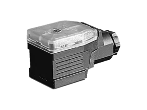 MUW-200 / 250Conditioner for LWH and TLH in the connector box, output 0…10 V, 0…20 mA or 4…20 mA, IP65.View technical specifications →
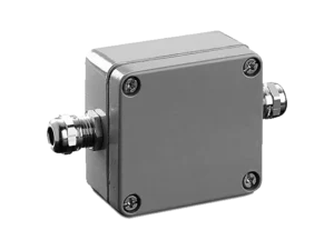 MUK-350field conditioner, output 0…10 V, ±10 V, 0…20 mA or 4…20 mA, IP66.View technical specifications →
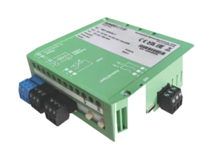 MUP-410DIN rail conditioner with teach-in, galvanic isolation and default 4…20 mA output.View technical specifications →
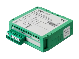 MUP-080MUP-100 / 150 and MUP-110 / 160: DIN rail, output 0…10 V or 4…20 mA; adjustable in the latter two and with insulation in MUP-150 and MUP-160.View technical specifications →
 T/TSTEX and LWG: potentiometrics with 25…150 mm, 10…300 mm and 50…750 mm stroke, with cursor ≤ 1 µA.View technical specifications →
More options in the category linear potentiometer.
Documentation and related cases
- Potentiometers: Technical Definitions by Novotechnik (PDF, English)
- Novotechnik sensors with IO-Link interface (PDF, English)
- All technical information about GUEMISA
Frequently Asked Questions
Can I connect a linear potentiometer directly to the PLC?
Yes, if the PLC has a high-impedance 0-10V input and the trace is powered with a stable 10V voltage. If the input loads the cursor above 1µA, the reading loses accuracy and a voltage conditioner is preferable.
What cursor current can a potentiometric transducer handle?
The LWH, TLH, T/TS, LWG and TEX datasheets recommend a maximum of 1 µA and give 10 mA as the maximum current in case of failure.
When is 4…20 mA preferable to 0…10 V?
With long cables, electrical noise, or the need to detect cable breakage, because 0 mA indicates a fault.
Which conditioner goes with LWH or TLH?
The MUW-200 or MUW-250 mounts in the DIN 43650 connector box next to the sensor. The 200 series has fixed range and zero; the 250 series has adjustable range and zero.
Send us the application, race or reference you have and we will tell you the model and your order code.