



















SAE J1939 plug-in flange magnetostrictive transducer TM1
- Manufacturer: Novotechnik
- Category: Displacement, SENSORS, Magnetostrictive Linear Transducer, Linear Transducers
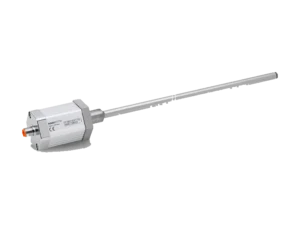
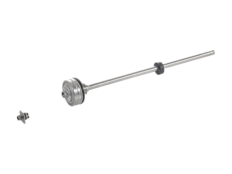
Novotechnik TM1 SAE J1939 plug-in flange transducer. NOVOSTRICTIVE technology, contactless.
Absolute linear magnetostrictive transducer with stainless steel flange welded to the rod. Stroke from 50 to 2000 mm. Working pressure up to 350 bar. Passive annular position marker. Industrial and mobile application versions.
Key points
- Working pressure up to 350 bar, peak pressure up to 450 bar
- Unlimited mechanical life
- No speed limit for the position marker
- Absolute exit
Technical Frequently Asked Questions
What can be connected to the TM1 SAE J1939 plug-in flange transducer?
It can be connected to Novotechnik M12 connectors and cables and Novotechnik linear sensor positioners (magnets and cursors).
How do I order the TM1 SAE J1939 plug-in flange transducer?
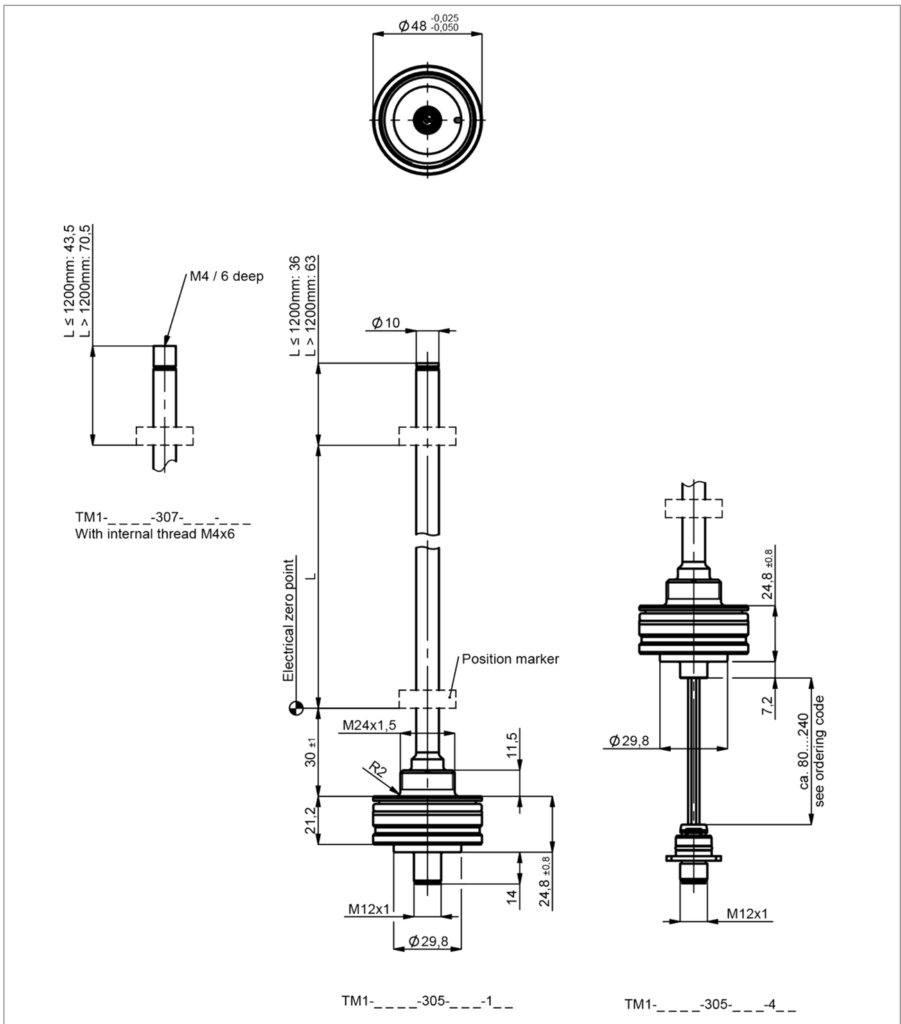
The order code has six fields: stroke (mm), mechanical version, interface, parameters, speed, and connection. For example, TM1-0500-305-J14-106 is the version with a 500 mm electrical range, Ø 48 mm plug-in flange, CAN SAE J1939, 1x position and 1x speed, 250 kBaud, and a 5-pin M12x1 connector. All the options for each field are available in the order code configurator on this page.
Under what conditions does the TM1 SAE J1939 plug-in flange transducer operate?
Operating temperature: -40 … +105 °C. Protection: IP67.
Properties
| Feature | Specification |
|---|---|
| Description | |
| Flange | Stainless steel 1.4307 / AISI 304L |
| Flange cover | AlSiMgBi |
| Rod | Stainless steel 1.4571 / AISI 316Ti |
| Watertightness | FKM 80 O-ring, PTFE support ring |
| Assembly, Industrial | Plugged in and secured in position with M5 ISO 4026 set screw |
| Assembly, Mobile Applications | Plugged into cylinders, fixed in position with M5 ISO 4026 set screw |
| Electrical connection, Industrial | M12x1 connector, A-coded / M12x1 connector system, A-coded, with wires |
| Electrical connection, Mobile applications | M12x1 connector, A-coded / M12x1 connector system, A-coded, with wires |
| Electrical data | |
| Measured variables | Position, speed, and temperature |
| Electrical range (L dimension) | 0 … 50 mm up to 0 … 2000 mm |
| Speed measurement range | 25 … 1000 mm/s |
| Protocol | CAN SAE J1939 |
| Programmable parameters | Position offset, averaged, transmission speed, transmission mode, transmission cycle, origin direction |
| Address (Node ID) | 128 … 247 (dynamic address assignment) |
| Transmission speed | 250, 500 kBaud |
| Update frequency (output) | 1 kHz (internal measurement frequency 0.5 kHz) |
| Absolute linearity | ≤ ±0.04 % FS (min. 300 µm) |
| Electrical zero point tolerance | ±1 mm |
| Position resolution | ≤ 0.1 mm |
| Speed resolution | 2 mm/s |
| Repeatability | ≤ ±0.1 mm |
| Hysteresis | ≤ ±0.1 mm |
| Temperature error | ≤ ±15 ppm/K (min. 0.01 mm/K) |
| Supply voltage Ub | 12/24 VDC (8 … 34 VDC) |
| Power supply voltage ripple | ≤ 10 % Ub |
| No-load consumption | < 1.5 W |
| Overvoltage protection | 40 VDC (6 s) |
| Reverse polarity protection | Yes (power lines and outlets) |
| Short circuit protection | Yes (all outputs connected to GND and the supply voltage) |
| Insulation resistance (500 VDC) | ≥ 10 MΩ |
| Internal bus termination | No (120 Ω internal load resistance, on request) |
| Environmental conditions | |
| Maximum working speed | Mechanically unlimited |
| Vibration IEC 60068-2-6 | 20 g, 10 … 2000 Hz, Amax = 0.75 mm |
| IEC 60068-2-27 Shock | 100 g, 11 ms (one stroke) |
| DIN EN 60529 protection | IP67 |
| DIN EN 60529 protection, M12 connector system fixed to cylinder | IP69 |
| Working temperature | -40 … +105 °C |
| Operating temperature, M12 connector system | -40 … +85 °C |
| Working humidity | 0 … 95 % HR (non-condensing) |
| Working pressure | ≤ 350 bar |
| Pressure spikes | ≤ 450 bar |
| Bursting pressure | > 700 bar |
| Life | Mechanically unlimited |
| MTTF (IEC 60050) | 391 years |
| Traceability | Serial number on the label: production batch of the sensor assembly and its components |
| EMC, Industrial version | |
| EN 61000-4-2 ESD, discharge by contact | 4 kV |
| EN 61000-4-2 ESD, air discharge | 8 kV |
| EN 61000-4-3 Electromagnetic fields (RFI) | 10 V/m |
| EN 61000-4-4 Fast transients (burst) | 1 kV |
| EN 61000-4-6 Conducted disturbances (HF fields) | 10 V ef. |
| EN 55016-2-3 Radiated disturbances | Industrial and residential area |
| EMC, Mobile Applications version | |
| ISO 10605 ESD (handling) | 8 kV |
| ISO 10605 ESD (component) | 15 kV |
| ISO 11452-2 Radiated HF fields | 100 V/m |
| ISO 11452-4 BCI (mass current injection) | 200 mA |
| CISPR 25 Radiated emission | Level 4 |
| ISO 7637-2 Transient emissions | Level 1/2 |
| ISO 7637-2 Pulses on the feed lines (1, 2a, 2b, 3a, 3b) | Level 4 |
| ISO 7637-3 Pulses on output lines (3a, 3b) | Fast Level 2 |
| ISO 16750 Pulses on power lines, startup profile | Level 4 with 12V; Level 3 with 24V |
| ISO 16750 Pulses on power lines, Load dump A | +200 V |
| EN 13309 Construction machinery | Emission and disturbance resistance: exceeds E1 requirements |
| ISO 14982 Agricultural and forestry machinery | Emission and disturbance resistance: exceeds E1 requirements |
| Option | Meaning |
|---|---|
| Example: TM1-0500-305-J14-106 = 500 mm electrical range, Ø 48 mm plug-in flange, CAN SAE J1939, 1x position and 1x speed, 250 kBaud and 5-pole M12x1 connector. | |
| 1. Electrical range (mm) | |
| 0050 … 2000 | Standard, 25 mm increments; other lengths available upon request |
| 2 · Mechanical version | |
| 305 | Plug-in flange Ø 48 mm |
| 307 | Plug-in flange Ø 48 mm with M4x6 internal thread at the end of the rod (7.5 mm longer) |
| 3 · Electrical interface | |
| J | CAN SAE J1939 |
| 4 · Interface parameters | |
| 1 | 1x position, 1x speed |
| 5 · Transmission speed | |
| 3 | 500 kBaud |
| 4 | 250 kBaud |
| 6. Electrical connection | |
| 106 | M12x1 connector, 5 poles |
| 468 … 484 | M12x1 connector system, 5 poles, with wires of 80, 120, 160, 200 or 240 mm (468, 472, 476, 480, 484); Industrial: for installation on a cylinder only |
| The code is formed using one option from each field, in the order shown in the example. Contact us and we will confirm the exact reference. | |
Related documentation, cases, and guides
Technical documentation
- Novotechnik General Catalogue: Linear and Angular Position Sensors
- Technical definitions of potentiometers: linearity, RGV and hysteresis
- Novotechnik position sensors with IO-Link interface
- Position sensors for valves and actuators: Novotechnik series
- Novotechnik linear and rotary sensors for automotive applications
Other products