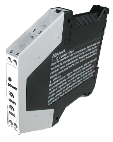
He Novotechnik potentiometer signal conditioner MUP-110/MUP-160 converts the signal from linear and rotary potentiometric position sensors into a normalized analog output of 0…10 V, 0…20 mA or 4…20 mA. This allows you to connect a measuring potentiometer to a PLC, a data acquisition card, an indicator, or an industrial control system.
The family consists of the MUP-110, without galvanic isolation, and the MUP-160, with galvanic isolation between the power supply and the other terminals. Both models power the sensor, read the cursor position with virtually no load, and transform its linear or angular movement into a proportional, stable, and easy-to-process signal.
- Entrance: potentiometric position sensors with resistance ≥ 700 Ω.
- Departures: 0…10 V, 0…20 mA or 4…20 mA, according to reference.
- Feeding: 24 VDC ±20 %.
- Adjustment: Zero and range adjustable via front trimmers.
- Precision: typical linearity of the 0.01 % full scale.
- Mounting: compact housing for 35 mm DIN rail.
What is a potentiometer signal conditioner?
A potentiometer signal conditioner is an electronic module that powers a potentiometric sensor, measures the voltage generated by the position of its wiper, and converts it into a standardized analog signal. This conversion allows the measured displacement or angle to be directly interpreted by industrial equipment with voltage or current inputs.
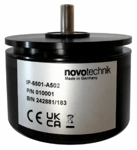
The MUP-110 and MUP-160 are specially designed to work with linear potentiometric sensors, rotary potentiometric sensors, and resistive position transducers. They are not simple universal resistance converters: they provide a stable reference to the potentiometer and perform a proportional reading of its cursor position.
Potentiometer conversion to 4–20 mA, 0–20 mA or 0–10 V
The direct signal from a potentiometer can be difficult to transmit or connect to an industrial analog input. The Novotechnik signal conditioner transforms this signal into one of the standardized formats commonly used by PLCs, indicators, and data acquisition systems:
- Output 4…20 mA: appropriate for transmitting the position measurement by means of a current signal.
- Output 0…20 mA: Suitable for control equipment that uses this analog range.
- Output 0…10 V: Suitable for PLCs and indicators with analog voltage input.
Each output corresponds to a different reference. The signal is not selected via switches or software, so the appropriate version must be chosen when ordering.
Differences between MUP-110 and MUP-160
| Model | Galvanic isolation | Available departures |
|---|
| MUP-110 | Without galvanic isolation | 0…10 V, 0…20 mA or 4…20 mA |
| MUP-160 | Between the power supply and the other terminals | 0…10 V, 0…20 mA or 4…20 mA |
He MUP-110 It is used when the installation does not require galvanic isolation between the power supply and the measuring circuit. MUP-160 It incorporates a DC/DC transformer that provides isolation between the power terminals and the rest of the connections.
It is important to note that the MUP-160's isolation separates the power supply from the signal circuit. It does not provide independent isolation between the potentiometer input and the analog output.
References available for MUP-110 and MUP-160
- MUP-110-0: 0…20 mA output, uninsulated, P/N 400054010.
- MUP-110-1: 0…10 V output, uninsulated, P/N 400054011.
- MUP-110-4: 4…20 mA output, uninsulated, P/N 400054014.
- MUP-160-0: 0…20 mA output, with insulation, P/N 400054060.
- MUP-160-1: 0…10 V output, with insulation, P/N 400054061.
- MUP-160-4: 4…20 mA output, with insulation, P/N 400054064.
Power supply and reading of the potentiometric sensor
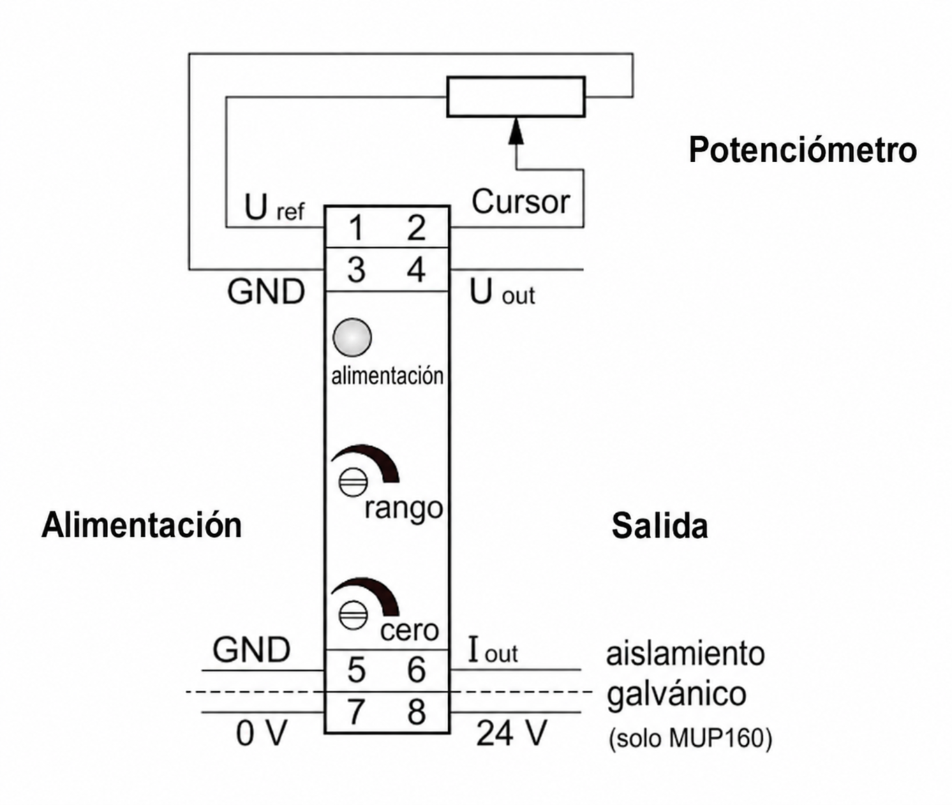
The conditioner provides the potentiometer with an internal reference voltage of 10 VDC, highly stable and protected against short circuits. The voltage present at the cursor is measured by a high-impedance input greater than 10 MΩ, reducing the load applied to the sensor to virtually zero.
This system leverages the accuracy and stability of conductive plastic potentiometers used in position measurement. The resulting signal can be sent to the control equipment as an output proportional to the linear displacement or angle of the sensor.
Zero point and measurement range adjustment
The MUP-110/160 incorporates two front trimmers for independent adjustment of the point zero and the range or gain. The zero can be shifted between −30 % and +20 %, while the gain can be adjusted between 0.65 and 2 times.
Thanks to this adjustment, it's possible to scale a portion of the potentiometer's range to obtain the full output signal. For example, the beginning of the movement can be associated with 0 V, 0 mA, or 4 mA, and the end with 10 V or 20 mA, always within the device's regulation limits.
Calibration is performed manually using the zero and range trimmers. The MUP-110 and MUP-160 They do not have a teach-in function, programming buttons, or configuration via DIP switches..
Measurement accuracy and stability
The conditioners offer a typical linearity of 0.01 % FS and a maximum linearity of 0.05 % of full scale. Its typical temperature coefficient of 20 ppm/K helps to maintain signal stability under variations in ambient temperature.
The current output versions support a maximum load of 500 Ω. In the voltage output versions, the maximum output current is 2 mA. The device incorporates reverse polarity protection and operates on a 24 VDC ±20 % power supply.
Applications of the MUP-110/160 conditioner
- Conversion of a potentiometer to 4…20 mA.
- Conversion of a potentiometer to 0…10 V.
- Position measurement with potentiometric linear sensors.
- Angular measurement with potentiometric rotary sensors.
- Connecting position sensors to PLC analog inputs.
- Integration into SCADA systems and data acquisition.
- Control of displacements, travels and mechanical positions.
- Test benches and testing equipment.
- Industrial machinery and automated lines.
- Modernization of existing facilities with potentiometric sensors.
DIN rail mounting
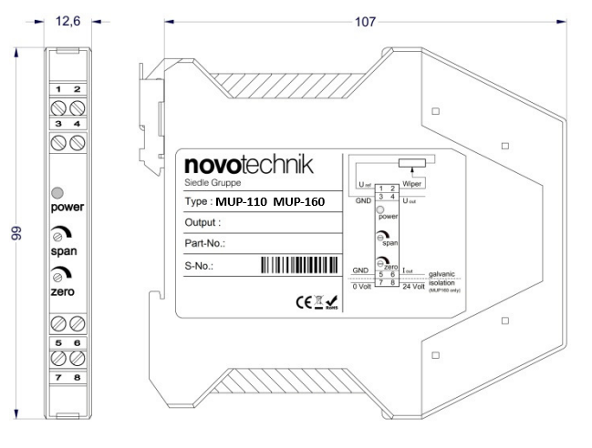
The electronics are integrated into a polyamide housing with dimensions of 107 × 99 × 12.6 mm. Its width of only 12.6 mm allows for the installation of several air conditioners while taking up little space inside the electrical panel.
The unit is mounted on a 35 mm DIN rail according to DIN EN 60715. The plug-in terminals accept conductors up to 2.5 mm². The device operates between +5 and +70 °C and has IP50 protection on the housing and IP00 protection on the terminals.
How to choose the right model
The selection must be made in two steps. First, it is determined whether the analog input of the PLC or the receiving equipment requires a signal of 0…10 V, 0…20 mA or 4…20 mA. Next, a decision is made as to whether the power supply should be galvanically isolated from the signal circuit.
- Select one MUP-110 if you don't need galvanic isolation.
- Select one MUP-160 if you need to isolate the power supply from the rest of the circuit.
- Select the suffix -0 to obtain an output of 0…20 mA.
- Select the suffix -1 to obtain an output of 0…10 V.
- Select the suffix -4 to obtain an output of 4…20 mA.
GUEMISA can help you select the right reference depending on the potentiometric sensor, the path used, the analog input of the PLC, and the electrical conditions of the installation.
Frequently Asked Questions about the MUP-110/160
What is the difference between the MUP-110 and the MUP-160?
The MUP-110 does not incorporate galvanic isolation. The MUP-160 isolates the power terminals from the other connections using a DC/DC transformer.
Can I convert the signal from a potentiometer to 4–20 mA?
Yes. To obtain an output of 4…20 mA, the references MUP-110-4, without isolation, or MUP-160-4, with galvanic isolation, should be used.
Which model provides a 0–10 V output?
The MUP-110-1 and MUP-160-1 models provide an output of 0…10 V. The difference between them is the addition of galvanic isolation in the MUP-160-1.
Can the output be changed after purchasing the equipment?
No. The output type is determined by the requested reference and cannot be changed by software, DIP switches, or pushbuttons.
Is it possible to adjust only part of the travel?
Yes. The zero and gain adjustments allow scaling the sensor's travel within the specified regulation limits.
Does it work for any variable resistor?
It is specifically designed for potentiometric position sensors connected as a voltage divider and with a resistance equal to or greater than 700 Ω. For other resistive sensors, compatibility must be checked beforehand.