TF1 SSI Contactless Inductive Linear Transducer
- Manufacturer: Novotechnik
- Category: Displacement, SENSORS, Linear Transducers
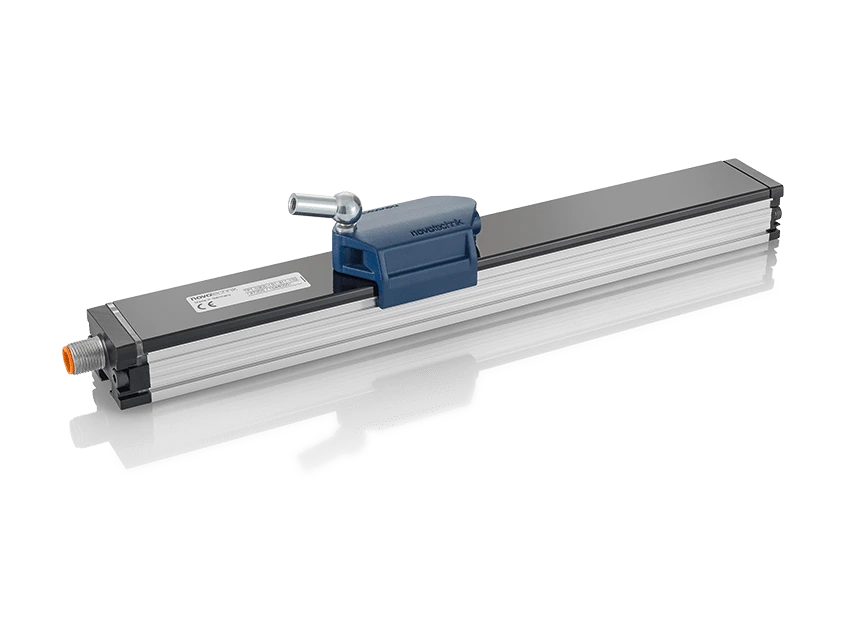
Novotechnik TF1 SSI inductive transducer. NOVOPAD inductive technology, contactless.
Non-contact linear inductive position transducer with active floating position marker. Stroke from 100 to 1000 mm. Reproducibility up to 5 µm. IP67 protection. Principle: emitter and receiver coils on the same board; the marker induces a current in the receivers, with sine/cosine structures on a thick and a thin track.
Key points
- Unlimited mechanical life (with floating placeholder)
- Refresh rate: 10 kHz
- Reproducibility: up to 5 µm
- IP67 protection: a GORE membrane equalizes pressure in response to temperature changes
Technical Frequently Asked Questions
What can be connected to the SSI TF1 inductive transducer?
It can be connected to Novotechnik M12 connectors and cables and Novotechnik linear sensor positioners (magnets and cursors).
How do I order the TF1 SSI inductive transducer?
The order code has six fields: stroke (mm), mechanical version, interface, signal, resolution, and connection mode. For example, TF1-0800-001-2A2-102 is the version with an 800 mm electrical range, profile, 24-bit SSI in Gray code, 5 µm resolution in Balanced mode, and an 8-pin M12x1 connector. All the options for each field are available in the order code configurator on this page.
Under what conditions does the TF1 SSI inductive transducer operate?
Operating temperature: -40 … +85 °C. Protection: IP67, with GORE membrane pressure equalization, with the connector fixed.
Properties
| Feature | Specification |
|---|---|
| Lengths | |
| Electrical range, level B | 0100 … 1000 mm, in 100 mm increments; other lengths available upon request |
| Housing length, dimension A | level B + 76.5 mm |
| Mass | 220 + 1.1 x B (B in mm) g |
| Description | |
| Housing | Anodized aluminum AlMgSi0.5 F22, 3.3206.71 |
| Inner casing | PA6 GF30 |
| End flanges | Aluminum G AlSi12Cu1 (FE) |
| Status indicator (LED) | PC |
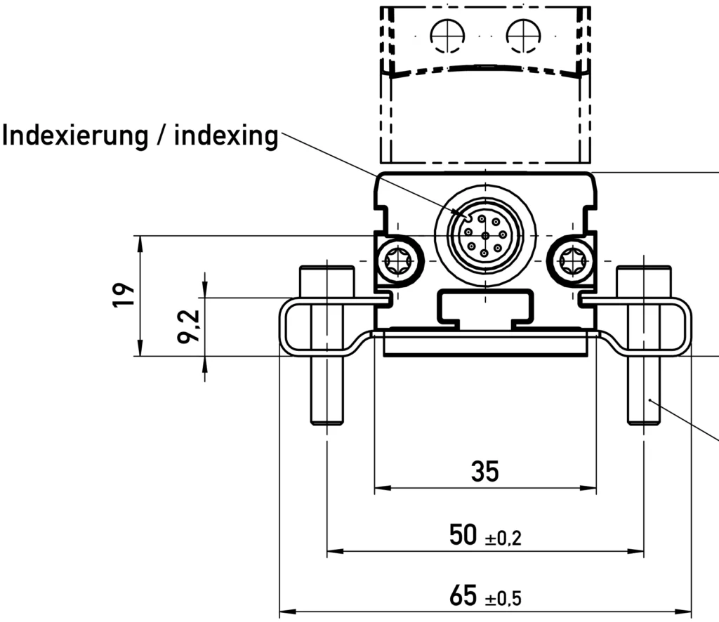
| Mounting | Adjustable flanges (included) or slot nut, e.g. M8 DIN 439 nut |
| Placeholder | Floating, made of plastic; or guided, made of plastic, with angular or axial articulation |
| Electrical connection | M12x1 8-pole shielded connector |
| Electronics | The connector housing is attached to the sensor housing; the housing is capacitively decoupled from the electronics. |
| Others | 2 Multifunction LEDs as an indicator of operating voltage and status |
| Electrical data | |
| Electrical range (dimension B) | 0100 … 1000 mm |
| Protocol | 24-bit and 25-bit SSI |
| Tickets | RS422, CLK lines galvanically isolated by optocouplers |
| Monoflop time™ | 20 µs |
| Coding | Gray (includes position and diagnostic data, Data+E+W), binary |
| Update frequency | > 10 kHz |
| Resolution (LSB) | 1, 5 or 10 µm |
| Reproducibility, High precision mode, dimension B ≤ 400 mm | < 5 µm |
| Reproducibility, High precision mode, dimension B > 400 mm | < 8 µm |
| Reproducibility, Balanced mode, dimension B ≤ 400 mm | < 10 µm |
| Reproducibility, Balanced mode, dimension B > 400 mm | < 15 µm |
| Reproducibility, High speed mode, dimension B ≤ 400 mm | < 20 µm |
| Reproducibility, High speed mode, dimension B > 400 mm | < 40 µm |
| Signal propagation delay, High precision mode | < 3 ms |
| Signal propagation delay, Balanced mode | < 1 ms |
| Signal propagation delay, High speed mode | < 0.2 ms |
| Hysteresis, High Prec mode | ≤ 5 µm |
| Hysteresis, Balanced mode | ≤ 10 µm |
| Hysteresis, High speed mode | ≤ 10 µm |
| Absolute linearity | ≤ ±100 µm |
| Electrical zero point tolerance | ±1 mm |
| Temperature coefficient (temperature error) | ≤ 15 ppm/K (min. 0.01 mm/K) |
| Supply voltage | 24 (18 … 32) VDC |
| Power supply voltage ripple | ≤ 10 % Vss |
| No-load consumption | 2.4 W |
| Overvoltage protection | 36 VDC (permanent) |
| Reverse polarity protection | Yes, up to the maximum supply voltage. |
| Short circuit protection | Yes (outputs to GND and supply voltage up to 7V) |
| Ohmic load at the outlets | > 120 Ω |
| Clock frequency | 60 … 1500 kHz |
| Maximum clock frequency depending on cable length | <3m: 1400kHz; < 10m: 1000kHz; <50m: 600kHz; < 100m: 350kHz; < 200m: 200kHz; < 400m: 100kHz |
| Insulation resistance (500 VDC) | ≥ 10 MΩ |
| Signal with broken cable | No communication |
| Signal with missing placeholder (codes 2A … 2D) | Error Bit 2 = 1, signal = -2097150 |
| Signal with position marker outside the measurement or working range | Warning Bit 1 = 1 |
| Environmental conditions | |
| Maximum operating speed with valid output signal | 10 m/s |
| Maximum operating acceleration with valid output signal | 200 m/s² |
| IEC 60068-2-27 Shock | 100 g (11 ms), one stroke |
| Vibration IEC 60068-2-6 | 20 g (5 … 2000 Hz, Amax = 0.75 mm) |
| DIN EN 60529 protection | IP67, with GORE membrane pressure equalization, with the connector fixed |
| Life | Mechanically unlimited (with floating placeholder) |
| Working temperature | -40 … +85 °C |
| Storage temperature | -40 … +85 °C |
| Working humidity | 0 … 95 % HR (non-condensing) |
| MTTF (IEC 60050) | 150 years |
| Accordance | EC |
| Electromagnetic compatibility | |
| EN 61000-4-2 | Electrostatic discharges (ESD) 4 kV, 8 kV |
| EN 61000-4-3 | Electromagnetic fields 10 V/m |
| EN 61000-4-4 | Fast transients (burst) 1 kV |
| EN 61000-4-6 | Conducted disturbances induced by RF fields 10 V rms. |
| EN 55016-2-3 | Radiated disturbances, class B |
| Option | Meaning |
|---|---|
| Example: TF1-0800-001-2A2-102 = 800 mm electrical range, profile, 24-bit SSI in Gray code, 5 µm resolution in Balanced mode and 8-pole M12x1 connector. | |
| 1. Electrical range (mm) | |
| 0100 … 1000 | Standard, 100 mm steps; others, on request |
| 2 · Mechanical version | |
| 001 | Profile |
| 3 · Electrical interface | |
| 2 | SSI |
| 4 · SSI output signal (2__) | |
| TO | SSI 24-bit, Gray |
| B | SSI 25 bit, Gray |
| C | SSI 24 bit, binary |
| D | SSI 25 bit, binary |
| 5 · High precision mode | |
| 4 | Resolution 1 µm |
| 5 | 5 µm resolution |
| 6 | Resolution 10 µm |
| 5 · Balanced Mode | |
| 1 | Resolution 1 µm |
| 2 | 5 µm resolution |
| 3 | Resolution 10 µm |
| 5 · High speed mode | |
| 7 | Resolution 1 µm |
| 8 | 5 µm resolution |
| 9 | Resolution 10 µm |
| 6. Electrical connection | |
| 102 | M12x1 connector, 8 poles |
| The code is formed using one option from each field, in the order shown in the example. Contact us and we will confirm the exact reference. | |
Related documentation, cases, and guides
Technical documentation
- Novotechnik General Catalogue: Linear and Angular Position Sensors
- Technical definitions of potentiometers: linearity, RGV and hysteresis
- Novotechnik position sensors with IO-Link interface
- Position sensors for valves and actuators: Novotechnik series
- Novotechnik linear and rotary sensors for automotive applications
Other products