



















High-resolution wire displacement sensor from 1 to 5 m
- Manufacturer: DPF Sensors
- Category: Displacement, Linear Cable Encoder, Linear Encoders, Linear by thread, SENSORS, Wire displacement sensors
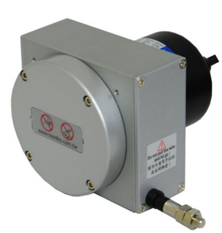
He DPF Sensors DLE-HR high-resolution wire displacement sensor It allows measuring movements and relative positions with paths of 1,000, 2,000, 3,000, 4,000 and 5,000 mm. It combines a retractable cable with an incremental encoder and an integrated pulse multiplier circuit, for automation, stroke control and test bench applications.
It offers resolutions of up to 0.005 mm/pulse in the 1 and 2 meter versions, and even 0.01 mm/pulse at 3, 4 and 5 meters. Its differential output line driver It allows the transmission of signals to PLCs, high-speed counters, and acquisition systems with compatible inputs.
- Available tours: 1, 2, 3, 4 and 5 m.
- Finer resolution: 5 µm per pulse at 1 and 2 m.
- Pulse multiplication: integrated circuit in the sensor.
- Differential signals: A, /A, B, /B, Z and /Z.
- Feeding: 5 VDC or 8–26 VDC, depending on the version.
- Maximum response frequency: 150 kHz.
- Protection: IP64.
Applications of the DLE-HR high-resolution wire encoder
He DPF Sensors DLE-HR high-resolution wire displacement sensor It allows measuring distances of up to 5 meters in applications such as:
- Tracking the position of long-travel linear axes and carriages.
- Height and stroke measurement on lifting platforms and tables.
- Extension control of telescopic mechanisms and extendable assemblies.
- Test benches for actuators and cylinders with up to 5 m stroke.
- Displacement recording in industrial door opening and closing tests.
- Supervision of the movement of moving parts in handling machinery.
- Tests requiring an incremental reading of up to 0.005 mm/pulse over distances of 1 and 2 m.
- Acquisition of position and direction of movement using differential encoder line driver inputs.
Travel distances of 1 to 5 meters and available resolutions
The resolution is selected when defining the supply reference. The available combinations depend on the route:
| PATH AND RESOLUTION | ||
|---|---|---|
| Route | Available resolutions | Pulses per millimeter |
| 1,000 and 2,000 mm | 0.02 / 0.01 / 0.008 / 0.005 mm/pulse | 50 / 100 / 125 / 200 |
| 3,000, 4,000 and 5,000 mm | 0.04 / 0.02 / 0.01 mm/pulse | 25 / 50 / 100 |
The integrated multiplier circuit increases the number of output pulses. The resolution indicates the offset corresponding to each pulse. It does not equate to absolute measurement accuracy. The declared repeatability is ±0.1 % of the full scale and ±1 count.
Line driver output and PLC connection
The encoder generates square wave signals with channels A and B in quadrature, which allow the displacement to be measured and its direction to be recognized. The channel Z It provides a reference signal. Each channel has its complementary signal to form the differential pairs. A–/A, B–/B and Z–/Z.
To connect it, the PLC, counter, or data acquisition equipment must have inputs compatible with the line driver and the application's pulse frequency. The sensor's power supply is selected from 5 VDC (L) and 8–26 VDC (H); This supply voltage should not be confused with the electrical level that the controller input accepts.
| LINE DRIVER CONNECTION | ||
|---|---|---|
| Sign | Cable color | Function |
| +V | Red | Feeding |
| 0 V | Black | Common power supply |
| TO | Blue | Incremental Channel A |
| B | Green | Incremental Channel B |
| Z | Yellow | Reference Z |
| /TO | Violet | Complementary signal of A |
| /B | Orange | Complementary signal of B |
| /Z | Brown | Complementary signal of Z |
| Screen | Mesh / armor | NC |
Retractable cable and mechanical characteristics
The measuring thread is SUS304 stainless steel, 0.7 mm in diameter and coated with nylon. An internal spring automatically retracts the cable as the moving element retracts.
- Declared breaking strength of the thread: 23 kg.
- Weight of the set: less than 1 kg.
- Electric wire: 1,000 mm in length and 4.5 mm in diameter.
- Typical lifespan: greater than 1 million cycles.
- Shock: 50 g for 11 ms.
- Vibration: 10–55 Hz, 1.5 mm VPP and maximum 10 g.
IP64 protection and operating conditions
The DLE-HR has IP64 protection and supports operating temperatures of 0 to 60 °C, with relative humidity of 35 to 90 %, non-condensing. The storage temperature is −20 to +70 °C.
DLE-HR references and version selection
The part number identifies the travel, resolution, power supply, and integrated multiplier. The suffix L corresponds to 5 VDC and H 8–26 VDC. Both options use differential line driver output.
| REFERENCES DPF SENSORS DLE-HR | |||
|---|---|---|---|
| Route | mm/pulse | 5VDC line driver | Line driver 8–26 VDC |
| 1,000 mm | 0,02 | DLE-HR-10-002A-L-M02 | DLE-HR-10-002A-H-M02 |
| 1,000 mm | 0,01 | DLE-HR-10-001A-L-M04 | DLE-HR-10-001A-H-M04 |
| 1,000 mm | 0,008 | DLE-HR-10-0008A-L-M05 | DLE-HR-10-0008A-H-M05 |
| 1,000 mm | 0,005 | DLE-HR-10-0005A-L-M08 | DLE-HR-10-0005A-H-M08 |
| 2,000 mm | 0,02 | DLE-HR-20-002A-L-M02 | DLE-HR-20-002A-H-M02 |
| 2,000 mm | 0,01 | DLE-HR-20-001A-L-M04 | DLE-HR-20-001A-H-M04 |
| 2,000 mm | 0,008 | DLE-HR-20-0008A-L-M05 | DLE-HR-20-0008A-H-M05 |
| 2,000 mm | 0,005 | DLE-HR-20-0005A-L-M08 | DLE-HR-20-0005A-H-M08 |
| 3,000 mm | 0,04 | DLE-HR-30-004A-L-M02 | DLE-HR-30-004A-H-M02 |
| 3,000 mm | 0,02 | DLE-HR-30-002A-L-M04 | DLE-HR-30-002A-H-M04 |
| 3,000 mm | 0,01 | DLE-HR-30-001A-L-M08 | DLE-HR-30-001A-H-M08 |
| 4,000 mm | 0,04 | DLE-HR-40-004A-L-M02 | DLE-HR-40-004A-H-M02 |
| 4,000 mm | 0,02 | DLE-HR-40-002A-L-M04 | DLE-HR-40-002A-H-M04 |
| 4,000 mm | 0,01 | DLE-HR-40-001A-L-M08 | DLE-HR-40-001A-H-M08 |
| 5,000 mm | 0,04 | DLE-HR-50-004A-L-M02 | DLE-HR-50-004A-H-M02 |
| 5,000 mm | 0,02 | DLE-HR-50-002A-L-M04 | DLE-HR-50-002A-H-M04 |
| 5,000 mm | 0,01 | DLE-HR-50-001A-L-M08 | DLE-HR-50-001A-H-M08 |
Example: DLE-HR-10-0005A-L-M08 This corresponds to 1,000 mm of travel, 0.005 mm/pulse, 5 VDC power supply and ×8 multiplication.
Frequently asked questions about the DLE-HR
Is the 0.005 mm/pulse resolution available at 5 meters?
No. It is offered at 1 and 2 m distances. At 3, 4 and 5 m, the finest resolution available is 0.01 mm/pulse.
Does a resolution of 5 µm equate to an accuracy of 5 µm?
No. It expresses the displacement corresponding to an output pulse. Resolution and repeatability are distinct characteristics.
Is it an absolute position sensor?
No. It's incremental: the control system obtains the displacement by counting pulses. The Z signal is an encoder reference and does not turn the equipment into an absolute sensor.
What data is needed to select a reference?
The travel distance, the desired resolution, the speed of movement, the available power supply, and the characteristics of the PLC or counter input.
How does it differ from the DLE-S?
The DLE-HR extends travel distances up to 5 meters and offers finer resolutions through integrated multiplication, a differential line driver output, and IP64 protection. DLE-S with 1,000 mm wire encoder It is another option in the range for one-meter journeys.
Sensor selection and configuration
Please tell us the path, resolution, and control system of your application. GUEMISA We help you select the DLE-HR reference and check the compatibility of your connection.
Properties
| TECHNICAL SPECIFICATIONS DPF SENSORS DLE-HR | |
|---|---|
| Model | DPF Sensors DLE-HR |
| Sensor type | Linear displacement sensor with high-resolution incremental encoder. |
| Available tours | 1,000 / 2,000 / 3,000 / 4,000 / 5,000 mm |
| Resolutions for 1 and 2 m | 0.02 / 0.01 / 0.008 / 0.005 mm/pulse |
| Pulses per millimeter at 1 and 2 m | 50 / 100 / 125 / 200, respectively |
| Resolutions for 3, 4 and 5 m | 0.04 / 0.02 / 0.01 mm/pulse |
| Pulses per millimeter at 3, 4 and 5 m | 25 / 50 / 100, respectively |
| Integrated multiplier | ×2 / ×4 / ×5 / ×8, depending on the path and resolution |
| Waveform | Square wave |
| Exit phases | A, /A, B, /B, Z and /Z |
| Output electronics | Differential line driver |
| Feeding | L: 5 VDC; H: 8–26 VDC |
| No-load consumption | ≤ 60 mA |
| Output capacity | 20 mA; residual voltage ≤ 0.5 V |
| Maximum response frequency | 150 kHz |
| A/B phase shift | 90° ±45° (T/4 ±T/8) |
| Phase Z | T ±T/2 |
| Up/down time | ≤ 1 µs |
| Declared repeatability | ±0.1 % of the full scale and ±1 count |
| Measuring cable | SUS304 stainless steel with nylon coating |
| Thread diameter | 0.7 mm |
| Declared breaking load | 23 kg |
| Vibration | 10–55 Hz / 1.5 mm PPV; maximum 10g |
| Shock | 50 g for 11 ms |
| Electric wire | Ø 4.5 mm; length 1,000 mm |
| Weight | < 1,000 g |
| Working temperature | 0 to 60 °C |
| Working humidity | 35–90 % HR, non-condensing |
| Storage temperature | -20 to +70 °C |
| Degree of protection | IP64 |
| Typical useful life | Greater than 1 × 10⁶ cycles |
Other products