



















RFC-4800 Non-Contact Angle Sensor SAE J1939
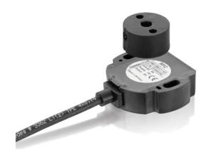
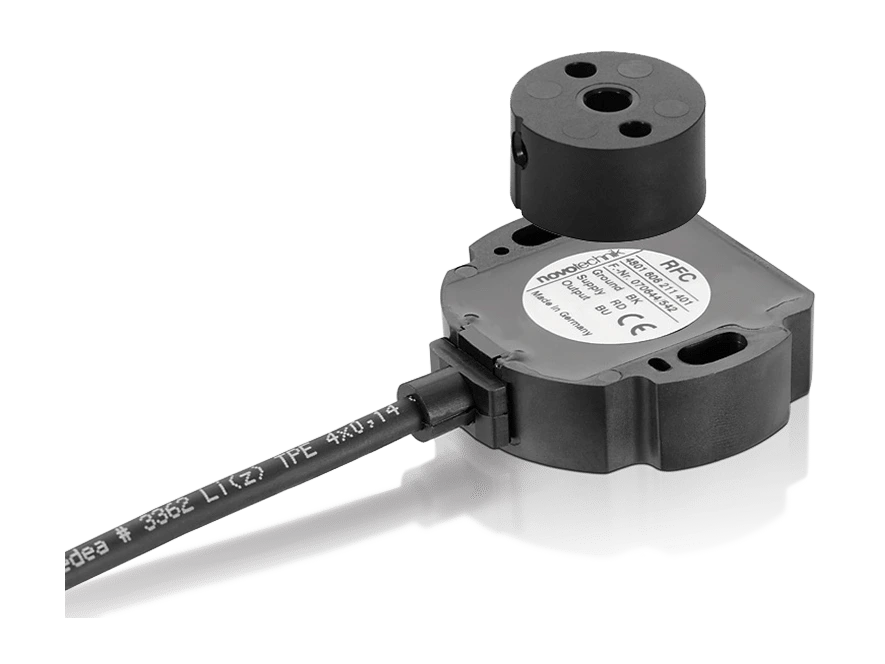
Novotechnik RFC-4800 SAE J1939 Angle Sensor. Non-contact, 360° Hall angle sensor in two mechanically decoupled pieces.
Non-contact Hall angle sensor, in two parts: sensor and magnetic position marker, without shaft or bearing. 360° measuring range. IP67, IP68, and IP69 protection. Measures through non-ferromagnetic material. Encapsulated electronics.
Key points
- Contactless Hall technology, 360° electrical range
- Two-piece design, mechanically decoupled
- IP67, IP68, IP69 protection
- 14-bit resolution
- Unlimited mechanical life
- Radiated HF fields 100 V/m (ISO 11452-2); exceeds E1 requirements
Technical Frequently Asked Questions
What can be connected to the RFC-4800 SAE J1939 angle sensor?
It can be connected to Novotechnik M12 connectors and cables and Novotechnik rotary sensor positioners (magnets).
How do I order the RFC-4800 SAE J1939 angle sensor?
The order code has 7 fields: mechanical version, digital interface, resolution, interface, parameters, speed, and connection. For example, RFC-4852-214-J14-232 is the version with round hole mounting, digital interface, 14 bits, CAN SAE J1939 with 1 position, 1 speed, and 1 revolution counter (one channel), 250 kBaud, and a 1 m shielded 4-pole cable. All the options for each field are available in the order code configurator on this page.
Under what conditions does the RFC-4800 SAE J1939 angle sensor operate?
Operating temperature: -40 … +105 °C, -25 … +85 °C (M12 connector). Protection: IP67 / IP68 / IP69, IP67 (M12 connector).
Properties
| Feature | Specification |
|---|---|
| Measurement and interface | |
| Measured variables | Position, speed, lap counter |
| Measuring range | 360° |
| Speed measurement range | 0 … 750 rpm |
| Number of channels | 1 / 2 |
| Protocol | CAN SAE J1939 |
| Programmable parameters | Position offset, counting direction, averaging, transmission speed, transmission mode, transmission cycle, origin direction, position resolution, speed resolution |
| Diagnosis | Activated (in case of error, the output signal falls outside the plausible signal range) |
| Origin address | 128 … 247 (dynamic address assignment) |
| Transmission speed | 250, 500 kBaud |
| Update frequency (output) | 1 kHz |
| Position resolution (in 360°) | 14 bits |
| Speed resolution (LSB) | 0.055°/s … 2.2°/s |
| Independent linearity | ≤ ±0.5 % FS |
| Repeatability | ≤ ±0.1° |
| Hysteresis | ≤ ±0.1° |
| Temperature error | ±0.2 % FS |
| Feeding and protection | |
| Supply voltage Ub | 12/24 VDC (8 … 34 VDC) |
| Current consumption when connected | ≤ 50 mA |
| Power consumed without load | < 0.4 W |
| Overvoltage protection | 45 VDC (permanent) |
| Reverse polarity protection | Yes (feed lines) |
| Short circuit protection | Yes (all outputs to GND and supply voltage up to 40 VDC) |
| Insulation resistance (500 VDC) | ≥ 10 MΩ |
| Internal bus termination | 120 Ω (optional) |
| Electromagnetic compatibility | |
| ISO 10605 ESD (handling/component) | 8 kV |
| ISO 11452-2 Radiated HF fields | 100 V/m |
| ISO 11452-4 BCI (mass current injection) | 200 mA |
| CISPR 25 Radiated emission | Level 3 |
| ISO 7637-2 Transient emissions | Level 4 |
| ISO 7637-2 Impulses in the feed lines (1, 2a, 2b, 3a, 3b, 4, 5) | Level 4 |
| ISO 7637-3 Impulses on output lines (3a, 3b) | Fast level 2, slow level 4 |
| E1 Requirements | Exceeds E1 requirements |
| Environmental conditions | |
| Vibration IEC 60068-2-6 | 20 g, 5 … 2000 Hz, Amax = 0.75 mm |
| IEC 60068-2-27 Shock | 50 g, 6 ms |
| DIN EN 60529 protection | IP67 / IP68 / IP69, IP67 (M12 connector) |
| Working temperature | -40 … +105 °C, -25 … +85 °C (M12 connector) |
| Life | Mechanically unlimited |
| MTTF (IEC 60050) | 843 years (one channel) or 819 years (two channels, per channel) |
| Mechanical data | |
| Housing | Temperature-resistant plastic |
| Fixation | 2 M4x20 socket head cap screws (included in the supply) |
| Mechanical tour | Continuous |
| Maximum working speed | Mechanically unlimited |
| Weight (without connection) | approx. 50 g |
| Electrical connection | Cable 2x 2x 0.34 mm² (AWG 22), TPE, shielded / M12x1 connector, A-coded, with cable L = 0.15 m / cable 4x 2x 0.25 mm² (AWG 24), TPE, shielded |
| Option | Meaning |
|---|---|
| Example: RFC-4852-214-J14-232 = round hole mounting, digital interface, 14 bits, CAN SAE J1939 with 1 position, 1 speed and 1 revolution counter (one channel), 250 kBaud and 1 m shielded 4-pole cable. | |
| 1 · Mechanical version | |
| 4851 | Mounting with elongated hole |
| 4852 | Mounting with round hole |
| 2-4 · interface, resolution, bus interface | |
| 2 | Interface: Digital interface |
| 14 | Resolution: 14 bits |
| J | Bus interface: CAN SAE J1939 |
| 5 · Interface parameters | |
| 1 | 1 channel: 1x position, 1x speed, 1x lap counter |
| 5 | 1 channel: 1x position, 1x speed, with 120 Ω termination |
| 2 | 2 channels: 2x position, 2x speed |
| 3 | 2 channels: 2x position, 1x lap counter |
| 6 | 2 channels: 2x position, 2x speed, with 120 Ω termination |
| 7 | 2 channels: 2x position, 1x revolution counter, with 120 Ω termination |
| 6. Transmission speed | |
| 3 | 500 kBaud |
| 4 | 250 kBaud |
| 7 · Electrical connection | |
| 231 | 4-pole cable, shielded, L = 0.5 m |
| 232 | 4-pole cable, shielded, L = 1 m |
| 236 | 4-pole cable, shielded, L = 3 m |
| 240 | 4-pole cable, shielded, L = 5 m |
| 432 | 8-pole cable, shielded, L = 1 m (CAN input/output) (*) |
| 511 | 5-pin M12x1 connector with shielded cable, L = 0.15 m |
| The code is formed using one option from each field, in the order shown in the example. Contact us and we will confirm the exact reference. | |

Related documentation, cases, and guides
Technical documentation
- Novotechnik General Catalogue: Linear and Angular Position Sensors
- Technical definitions of potentiometers: linearity, RGV and hysteresis
- Novotechnik position sensors with IO-Link interface
- Position sensors for valves and actuators: Novotechnik series
- Novotechnik linear and rotary sensors for automotive applications
Other products