
Technical guide · GUEMISA
To connect a linear position sensor to a PLC with a 4–20 mA signal, there are two options: a transducer with an integrated current output or a potentiometric transducer with a signal conditioner that converts the cursor voltage to 4–20 mA. The current output is chosen when the cable is long or the environment has electrical noise, and because it allows you to distinguish a cable break from an actual position.
The position is calculated in the PLC with the formula stroke × (I − 4 mA) / 16 mA. A value of 4 mA corresponds to the start of the stroke and 20 mA to the end.
Why 4…20 mA and not a voltage
Distance
A current signal is independent of the voltage drop in the cable: the transmitter forces the same current through the entire loop, whether the cable is 5 m or 200 m long. With a voltage signal of 0–10 V, the cable resistance and the PLC input impedance form a voltage divider that introduces error. As an order of magnitude, 100 m of 0.5 mm² cable adds up to about 7 Ω of round-trip resistance, which is negligible compared to a 250 Ω load.
Electrical noise
The power input has low impedance, so voltages induced by drives, contactors, or motors generate very small currents and have less of an impact on the measurement than with a high-impedance power input. Even so, a shielded cable with the braid connected according to the manufacturer's recommendations and kept separate from power cables is recommended.
Cable break detection
The starting point for the scale is 4 mA, not 0 mA («live zero»). If the cable is cut, the current drops to 0 mA, an off-scale value that the PLC may interpret as a fault. With a 0–10 V range, a broken cable and a position at the starting point both give 0 V and are indistinguishable.
Some transducers on the chips add their own error signal. The TF1 outputs less than 3.5 mA with a broken wire. The TM1 outputs 24 mA or more if the marker is out of range, and 3.5 mA or less if the GND wire is broken.
Two wires, three wires and maximum load
Two and three threads
In a two-wire loop sensor, the same conductors power the sensor and carry the signal; therefore, the signal never drops below 4 mA, as this current powers the electronics. In a three-wire loop, power, ground, and signal are carried on separate conductors. The Novotechnik transducers with a 4–20 mA output mentioned in this article have independent power supplies (24 V, or 8–32 V in the TM1) and do not function as a two-wire loop. If your installation only has a two-wire loop, this must be verified before selecting a sensor.
Maximum load
The load is the sum of the PLC's input resistance (for example, 250 Ω on a card with a shunt resistor) and the cable resistance. The connectors clearly indicate the maximum: no more than 500 Ω for TH1, TP1, TF1, LS1, FTI, and MUW. For TM1, the maximum is 500 Ω with a 24 V power supply and 250 Ω with a 12 V supply. With a 250 Ω input and a 20 Ω cable, the load is 270 Ω: it meets the 500 Ω limit, but not the 250 Ω limit for TM1 powered at 12 V.
Alternatives: 0…10 V and ratiometric output
- 0–10 V: suitable for short cables within the cabinet. Many transducers offer both outputs, such as the TE1, LS1, TF1, and TM1. The connectors require a minimum load of 5 kΩ or 10 kΩ on the voltage output.
- Ratiometric: the output is a percentage of the supply voltage (e.g., 10–90%). This is used when the same 5V supply powers both the sensor and the converter's reference voltage, and is common in vehicles. It is not suitable if the supply voltage varies and the converter has a different reference voltage.
- Digital (SSI, CANopen, IO-Link): The TH1 and TP1 are also offered with these interfaces, on their own separate cards. They avoid analog conversion, but require a compatible input module.
Integrated output or potentiometer with conditioner
A potentiometric transducer is a voltage divider: it delivers a voltage proportional to its position and requires a signal conditioner to convert it into a normalized signal. A transducer with an integrated output has the electronics inside the housing.
When is each option useful?
- Integrated output: a single component, less wiring, and a single cable to the PLC. This is common in long-running or high-pressure environments, such as magnetostrictive circuits.
- Potentiometer with conditioner: allows you to choose between very different stroke transducers and formats (LWH, TLH, or TEX) and change the output (0…10 V, ±10 V, 0…20 mA, 4…20 mA) without changing the sensor. The conditioner supplies the potentiometer with a stable reference and detects the cursor with almost no load.
Novotechnik Conditioners
- MUW-200/250: fits inside the DIN 43650 connector housing of LWH and TLH transducers. Output: 0…10 V, 0…20 mA or 4…20 mA; power supply: 18…30 VDC; IP65. The 200 series is fixed range; the 250 series is adjustable.
- MUK-350: IP66 die-cast aluminum housing, output 0…10 V, ±10 V, 0…20 mA or 4…20 mA, with adjustable zero and range, and 18…30 VDC power supply.
- MUP-080: DIN rail, output 0…10 V or 4…20 mA, load up to 500 Ω, without galvanic isolation.
- MUP-100/150 and MUP-110/160: DIN rail; the MUP-150 and MUP-160 models add galvanic isolation between power and output.
- MUP-410: DIN rail, microprocessor controlled, output 4…20 mA, 0…10 V or ±10 V.
Table of options with actual products
| Product | Principle | Career | Power output | Feeding | Protection |
|---|---|---|---|---|---|
| FTI 10 | Inductive, with feedback | 10 mm | 4…20 mA or 0…20 mA | 18…30 VDC | IP50 or IP67 |
| TE1 | Potentiometric with integrated processing | 25…150 mm | 4…20 mA (or 20…4 mA) | 16…30 V | IP40 |
| LS1 | Contactless inductive | 25…200 mm | 4…20 mA (or 20…4 mA) | 16…30 VDC | IP40 |
| TF1 | Contactless inductive | 100…1000 mm | 4…20 mA | 18…32 VDC | IP67 |
| TM1 | Magnetostrictive | 50…2000 mm | 4…20 mA | 8…32 VDC | IP67 |
| TH1 | Magnetostrictive, rod type | 50…4250 mm | 4…20 mA | 19…30 VDC | IP67 / IP68 |
| TP1 | Magnetostrictive, profile | 50…4250 mm | 4…20 mA | 19…30 VDC | IP67 / IP68 |
| LWH + MUW-200/250 | Potentiometer + conditioner | 50…900 mm | 4…20 mA | 18…30 VDC | IP55 (sensor), IP65 (MUW) |
| TLH + MUW-200/250 | Potentiometer + conditioner | 100…3000 mm | 4…20 mA | 18…30 VDC | IP40 or IP54 (sensor), IP65 (MUW) |
Which GUEMISA products are a good fit?
 TF1 analogstroke from 100 to 1000 mm, 4…20 mA with load up to 500 Ω, IP67 and signal less than 3.5 mA with the cable broken.View technical specifications →
 TM1 with plug-in flangestroke from 50 to 2000 mm, 4…20 mA, 8 to 32 VDC power supply and IP67.View technical specifications →
 TH1 analogfrom 50 to 4250 mm, 4…20 mA, 350 bar and IP67 / IP68, to be integrated into a hydraulic cylinder.View technical specifications →
 TP1 analogfrom 50 to 4250 mm, 4…20 mA, aluminum profile with floating or guided marker and IP67 / IP68.View technical specifications →
 TE1short stroke from 25 to 150 mm, 18 x 18 mm profile, 0…10 V or 4…20 mA.View technical specifications →
 LS1Inductive contactless from 25 to 200 mm, same 18 x 18 mm profile, voltage or current output.View technical specifications →
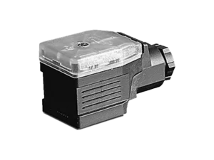 MUW-200/250Conditioner at the LWH and TLH transducer connector, 4…20 mA with load up to 500 Ω.View technical specifications →
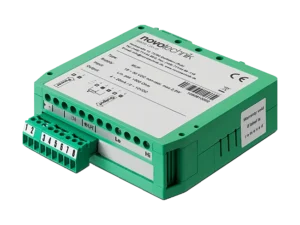 MUP-080DIN rail conditioner for any potentiometer from 0.5 to 100 kΩ, output 0…10 V or 4…20 mA.View technical specifications →
To see more models, check the category Linear transducers and the category Resistance converters and potentiometers.
Documentation and related cases
- Potentiometers: Technical Definitions by Novotechnik (PDF, English)
- Novotechnik sensors with IO-Link interface (PDF, English)
- Position and displacement sensors (report, PDF)
- All technical information about GUEMISA
Frequently Asked Questions
How do you convert from 4…20 mA to millimeters in the PLC?
It scales linearly: position = stroke × (I − 4 mA) / 16 mA. At an input with a resistance of 250 Ω, the board sees from 1 V to 5 V, and the scaling is configured with those values.
What does a reading below 4 mA mean?
This should not occur in a healthy sensor. It indicates a broken cable, power failure, or sensor error. Some transducers, such as the TF1 and TM1, explicitly indicate this with a current below 3.5 mA.
Can I use a 4…20 mA transducer with a 12 V power supply?
Only if the connector allows it. The TM1 accepts 8…32 VDC, but the maximum load drops to 250 Ω at 12 V. The others in the table are powered by 16 to 32 V, depending on the model.
What cable length does a 4…20 mA output support?
The signal itself supports long distances because the current is independent of length. The limit is determined by the total load, which must not exceed the maximum rating of the connector, and by noise. Shielded cable, kept separate from power cables, is recommended.
When is a potentiometer with a conditioner advisable?
When you need a type of stroke or mounting that doesn't exist with an integrated output, or when you want to choose the output signal later. With LWH or TLH, the MUW fits in the connector box and leaves the signal at 4…20 mA next to the sensor.
Send us the application, race or reference you have and we will tell you the model and your order code.