Schreiber SM30 LVDT sensor – Integrated electronics M30×1.5
- Manufacturer: Schreiber Messtechnik
- Category: Displacement, Amplified LVDTs, SENSORS, LVDT Sensors
The Schreiber SM30 is an inductive linear displacement LVDT sensor with integrated electronics. It features an M30×1.5 threaded housing and delivers an analog signal without an external LVDT conditioner. Applications include position, stroke, and motion measurement in industrial machinery, actuators, automation systems, and test benches.
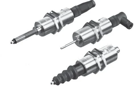
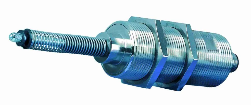
Manufacturer: Schreiber Messtechnik (Germany). Nominal strokes: 5, 10, and 15 mm. Linearity: 0.5% or 0.25% depending on the model. Construction: nickel-plated brass body, Ni-Fe alloy moving core, and integrated measuring electronics. Available with probe and protective bellows.
The SM30 family comprises the models SM301, SM302, SM303, SM304, SM305, SM306, SM307, and SM308. Outputs: 0–20 mA, 4–20 mA, ±10 V, or 0–10 V, with either rising or falling signal. The model also determines the supply voltage.
The M30×1.5 thread allows for mounting and axial adjustment of the sensor. 4–20 mA (SM303, SM304) or 0–10 V (SM307, SM308) output for industrial analog inputs.
Schreiber SM30 LVDT sensor models and references
1. Models SM301 to SM308: Analog outputs and power supply
The Schreiber SM30 series has eight electrical models. Each one determines the type of output signal and the direction of variation with respect to the core's movement.
| Model | Exit | Feeding | Sign | Central value |
|---|---|---|---|---|
| SM301 | 0–20 mA | 20–32 VDC | Growing | 10 mA |
| SM302 | 0–20 mA | 20–32 VDC | Decreasing | 10 mA |
| SM303 | 4–20 mA | 20–32 VDC | Growing | 12 mA |
| SM304 | 4–20 mA | 20–32 VDC | Decreasing | 12 mA |
| SM305 | ±10 VDC | ±13 to ±16 VDC | Growing | 0 V |
| SM306 | ±10 VDC | ±13 to ±16 VDC | Decreasing | 0 V |
| SM307 | 0–10 VDC | 20–32 VDC | Growing | 5 V |
| SM308 | 0–10 VDC | 20–32 VDC | Decreasing | 5 V |
Rising signal: increases when the stem moves toward the sensor connector. The falling version reverses this relationship.
The PLC's analog input must support the selected signal. The power supply must meet the reference requirements.
2. Order references SM30: stroke of 5, 10 and 15 mm
The Schreiber order code identifies the electrical model, nominal stroke, linearity class, and, where applicable, a mechanical option.
Structure: SM30X.STROKE.LINEARITY.OPTION
- X = 1 to 8: output type and signal direction.
- Stroke: 5, 10 or 15 mm.
- Class .1: linearity 0.25%.
- Class .2: linearity 0.5%.
- Option .T: execution as a probe.
- Option B: bellows execution.
The table details the code combinations for standard mobile kernel versions based on the datasheet nomenclature. Availability of each combination should be confirmed with the manufacturer.
| Model | 5 mm | 10 mm | 15 mm |
|---|---|---|---|
| SM301 | SM301.5.1 SM301.5.2 | SM301.10.1 SM301.10.2 | SM301.15.1 SM301.15.2 |
| SM302 | SM302.5.1 SM302.5.2 | SM302.10.1 SM302.10.2 | SM302.15.1 SM302.15.2 |
| SM303 | SM303.5.1 SM303.5.2 | SM303.10.1 SM303.10.2 | SM303.15.1 SM303.15.2 |
| SM304 | SM304.5.1 SM304.5.2 | SM304.10.1 SM304.10.2 | SM304.15.1 SM304.15.2 |
| SM305 | SM305.5.1 SM305.5.2 | SM305.10.1 SM305.10.2 | SM305.15.1 SM305.15.2 |
| SM306 | SM306.5.1 SM306.5.2 | SM306.10.1 SM306.10.2 | SM306.15.1 SM306.15.2 |
| SM307 | SM307.5.1 SM307.5.2 | SM307.10.1 SM307.10.2 | SM307.15.1 SM307.15.2 |
| SM308 | SM308.5.1 SM308.5.2 | SM308.10.1 SM308.10.2 | SM308.15.1 SM308.15.2 |
Manufacturer's example: SM303.10.2, 10 mm sensor, 4–20 mA scaling output and 0.5% linearity.
Another example of the order structure is SM301.10.2.T, with probe execution. For mechanical modifications and special versions, Schreiber can assign specific order codes.
3. M30×1.5 mounting, dimensions and mechanical construction
The SM30 incorporates a threaded cylindrical housing M30×1.5 with tightening zones for SW27 wrench. The main body has a nominal length of 70 mm according to the drawing in the technical data sheet.
The standard version rod has a diameter of 16 mm in the area indicated on the drawing and an M4 threaded end. Dimensions should be checked against the drawing corresponding to the selected variant, especially when a probe or bellows is ordered.
The housing is made of nickel-plated brass; the stem is stainless steel and the core is a Ni-Fe alloy. The connector is nickel-plated brass and its contacts are gold-plated brass.
The threaded mounting allows for adjusting the sensor's position on the bracket. Lateral stress on the rod should be avoided.
4. Measuring probe and version with protective bellows
The SM30 family offers optional mechanical configurations designed for different types of contact and protection:
- Version .T: probe execution for direct measurement of the displacement of a part using a measuring tip.
- Version .B: execution with protective bellows around the moving assembly.
The Schreiber drawing shows the probe construction with a reference length of 55 mm from the body and a maximum indicated dimension of 63.5 mm for the protruding assembly. These dimensions belong to the drawing of version .T and should not be confused with the nominal measuring stroke.
To select the mechanical execution it is necessary to define the stroke, the available space, the contact geometry and the environmental conditions of the installation.
5. Electrical connection of models SM301–SM308
The SM30 has a four-pin electrical connector. The pin assignment depends on the output model. The Schreiber datasheet shows the connection as seen from the sensor's own connector.
| Pin | SM301–SM304 / SM307–SM308 | SM305–SM306 |
|---|---|---|
| 1 | +UB | +UB |
| 2 | Not connected | 0 V |
| 3 | AI / UA (output) | UA (exit) |
| 4 | −UB (0 V) | −UB |
The SM305 and SM306 models require a symmetrical power supply. The remaining standard versions listed use a 20–32 VDC continuous power supply.
The data sheet also specifies protection against reverse polarity of the power supply.
6. Accuracy, measurement response, and environmental conditions
Linearity classes: 0.5% and 0.25%, depending on the reference. The integrated electronics convert the core displacement into a proportional current or voltage signal.
The documented general values are:
- Measurement frequency: 800 Hz, according to Schreiber data sheet.
- Thermal drift: less than 0.01%/°C.
- Operating temperature: −20 to +85 °C.
- Vibration resistance: 20 g RMS, with peaks of 50 g.
- Shock resistance: 250 g SRS, 20–2000 Hz.
- Protection: IP66 with additional connector mounted; the technical header also identifies IP66/IP67.
The manufacturer's reference conditions are an ambient temperature of +20 °C, the nominal power supply indicated for the version, and a stabilization period of 10 minutes after connecting the sensor.
The measurement frequency of 800 Hz does not correspond to the maximum response frequency of the entire system. In dynamic applications, the acquisition and filtering conditions must be verified.
7. Electrical load and output characteristics
The SM301–SM304 current output versions support a load resistance of 0 to 500 Ω and have a specified maximum power consumption of 60 mA.
The documentation indicates a residual ripple of less than 0.005 mA peak-to-peak, as well as a load dependence of less than 0.001% for a change of 100 Ω and a power dependence of less than 0.05% for a change of 1 V.
The SM305–SM308 voltage output versions require a load of at least 2 kΩ and have a maximum rated current of 50 mA. Their residual ripple is less than 5 mV peak-to-peak.
For the SM307/SM308 versions, a maximum residual voltage of 0.1 VDC is indicated.
8. Applications and selection compared to Schreiber SM31, SM32 and SM34
Applications of the SM30 as an LVDT displacement sensor with integrated analog output, without external conditioner:
- Stroke control of actuators and linear mechanisms.
- Position measurement in industrial machines.
- Monitoring the movement of moving parts.
- Measurement of displacements on test benches.
- Dimensional control with probe configurations.
- Integration of analog sensors into PLCs and acquisition systems.
- OEM equipment.
Other Schreiber series with integrated electronics: SM31 (programmable functions, similar threaded format), SM32 (square housing of 25×25 mm) and SM34 (miniature body of smaller diameter).
Selection criteria: travel distance, dimensions, output signal, power supply and installation requirements.
Frequently Asked Questions about the Schreiber SM30 LVDT
Which Schreiber SM30 models have a 4–20 mA output?
The SM303 and SM304 models provide 4–20 mA output. The SM303 has a rising signal and the SM304 a falling signal. Both require a 20–32 VDC power supply.
Which SM30 references have a 0–10 V output?
The SM307 and SM308 models offer 0–10 VDC output. The SM307 is step-up and the SM308 is step-down. The specified supply voltage is 20–32 VDC.
Is there a Schreiber SM30 with a bipolar ±10 V output?
Yes. The SM305 and SM306 models provide ±10 VDC output and require a symmetrical ±13 to ±16 VDC power supply.
Does the Schreiber SM30 need an external LVDT conditioner?
No. The measurement electronics are integrated and directly deliver the analog output of the chosen reference, with compatible power supply and acquisition input.
What races can the Schreiber SM30 measure?
The manufacturer's technical data sheet documents nominal travels of 5, 10 and 15 mm, with linearity classes of 0.5% or 0.25% depending on the reference.
What does the reference SM303.10.2 mean?
It is a Schreiber SM30 sensor with 4–20 mA scaling output, 10 mm nominal travel and 0.5 % linearity, according to the order example published by the manufacturer.
Are there SM30 versions with a probe or bellows?
Yes. The documentation includes a .T version with a probe and a .B version with a bellows. Its configuration must be confirmed when defining the complete reference.
Where can I buy Schreiber SM30 LVDT sensors in Spain?
Guemisa supplies Schreiber Messtechnik sensors in Spain: models SM301 to SM308.
Schreiber technical documentation and distribution in Spain
Dimensions, electrical diagram, connections, output characteristics and ordering nomenclature: Schreiber SM30 official technical sheet.
See also: amplified LVDT sensor category, LVDT sensor range and Schreiber Messtechnik in Guemisa.
Guemisa – Sensors and Instrumentation. Distribution of amplified LVDT sensors, inductive transducers and displacement measurement systems.
Properties
| Specification | Schreiber SM30 / SM301–SM308 |
|---|---|
| Manufacturer | Schreiber Meßtechnik GmbH, Germany |
| Sensor type | LVDT sensor / amplified linear displacement inductive transducer |
| Measurement technology | Differential inductive, Ni-Fe moving core |
| Conditioning electronics | Integrated into the sensor |
| Family | SM30 |
| Electric models | SM301 / SM302 / SM303 / SM304 / SM305 / SM306 / SM307 / SM308 |
| Nominal races | 5 / 10 / 15 mm |
| Accuracy according to technical specifications | <0.5 % or 0.25 % depending on the selected class |
| Precision code .1 | 0,25 % |
| Precision code .2 | 0,5 % |
| Mounting thread | M30×1.5 |
| Mounting wrench | SW27 |
| Standard body length | 70 mm according to Schreiber drawing |
| Front diameter indicated on drawing | Ø16 mm |
| Threaded rod end | M4 |
| SM301 / SM302 Output | 0–20 mA, increasing / decreasing |
| SM303 / SM304 Output | 4–20 mA, increasing / decreasing |
| SM305 / SM306 Output | ±10 VDC, increasing / decreasing |
| SM307 / SM308 Output | 0–10 VDC, increasing / decreasing |
| Power Supply SM301–SM304 | 20–32 VDC |
| SM305-SM306 Power Supply | Symmetrical ±13 to ±16 VDC |
| SM307–SM308 Power Supply | 20–32 VDC |
| Central value 0–20 mA | 10 mA |
| Central value 4–20 mA | 12 mA |
| Center value ±10 V | 0 V |
| Center value 0–10 V | 5 V |
| Load for current output | 0–500 Ω |
| Load for voltage output | ≥2 kΩ |
| Current consumption, mA output | Maximum 60 mA |
| Current consumption, output V | Maximum 50 mA |
| Residual ripple, mA output | <0.005 mA peak-to-peak |
| Residual curl, V outlet | <5 mV peak-to-peak |
| Residual voltage SM307 / SM308 | Maximum 0.1 VDC |
| Load dependency, mA output | <0.001 % for ΔRL = 100 Ω |
| Feeding dependency | <0.05 % for ΔUB = 1 V |
| Indicated measurement frequency | 800 Hz |
| Thermal drift | <0.01 %/°C |
| Operating temperature | -20…+85 °C |
| documented standard protection | IP66 with auxiliary connector mounted |
| Additional protection mentioned | IP67 in header of card; confirm execution |
| Vibration resistance | 20 g RMS, peaks of 50 g |
| Shock resistance | 250 g SRS, 20–2000 Hz |
| Housing | Nickel-plated brass |
| Stem | Stainless steel |
| Core | Ni-Fe Alloy |
| Connector | Four contacts; nickel-plated brass body |
| Electrical contacts | Gold-plated brass |
| Connections, current output / 0–10 V | 1 +UB / 2 NC / 3 output / 4 −UB (0 V) |
| Connections, output ±10 V | 1 +UB / 2 0 V / 3 output / 4 −UB |
| Optional execution .T | Measuring probe |
| Optional execution .B | With protective bellows |
| Example of a manufacturer's order | SM303.10.2 |
| Distributor in Spain | GUEMISA – Sensors and Instrumentation |
Related documentation, cases, and guides
Other products