
Technical guide · GUEMISA
Principle and factors of the installation
The conductive level control system is based on measuring the electrical resistance of the medium being monitored. Electrodes in contact with the medium collect this information by closing the electrical circuit between them and transmit it to the level relay, which then operates according to its operating mode.
Proper functioning depends on factors that may be related to each other:
- The type of deposit
- The resistivity/conductivity of the medium to be controlled
- The location of the electrodes in the tank
- The type of cable and its length
- Installing the cable from the sensor to the relay
- Electromagnetic interference that may be radiated by external elements
The guide assumes that the type of sensor has been chosen according to the mechanical characteristics and access to the tank, and that the relay fulfills the required level control function.
Common or reference electrode
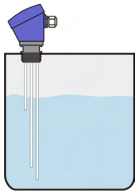
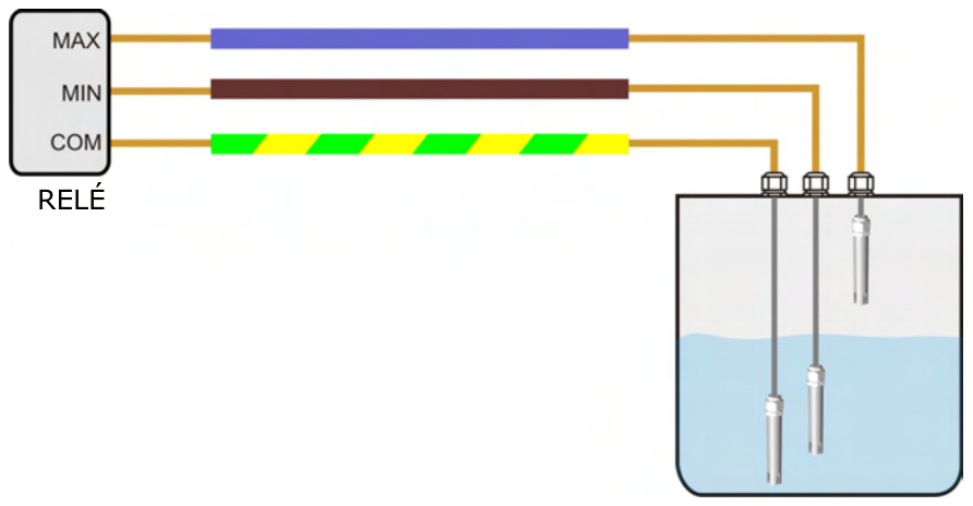
The resistivity reading of the medium is always taken between the common electrode and the other electrodes. Therefore, it must always be in contact with the medium: it is installed at the lowest point of the tank or immediately below the electrode that monitors the lowest point (minimum level or low level alarm).
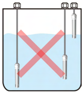
Ideally, it should be as close as possible to the other electrodes. The greater the distance between the common electrode and the others:
- The higher the resistivity being measured, the further it may fall from the relay's measurement range. Different relays are available for different resistivity ranges.
- Greater sensitivity to disturbances radiated by electromagnetic interference, which can cause unexpected effects on the level relay.
If the tank is metallic, it can be used as a common electrode because the medium is always in contact with it. It is advisable that the other electrodes be placed as close as possible to the tank walls.
| Deposit | Correct installation | Installation not recommended |
|---|---|---|
| Any type | The electrodes remain close to each other. | The electrodes remain away from the common electrode |
| Metal | The electrodes remain close to the common electrode, which is the tank wall. | The electrodes remain away from the common electrode, which is the tank wall. |
Recommended cable types
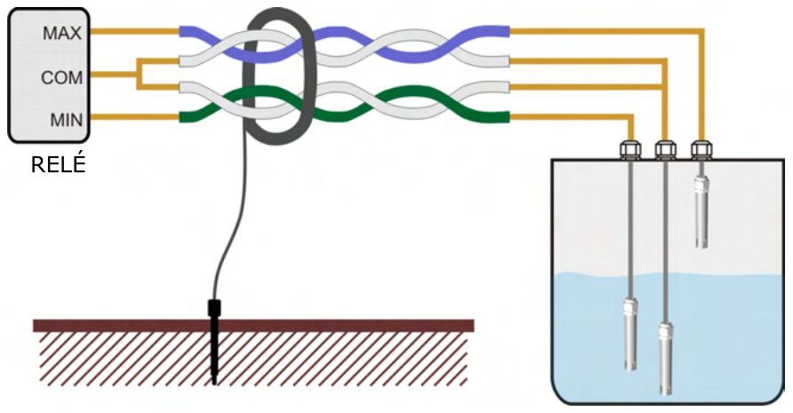
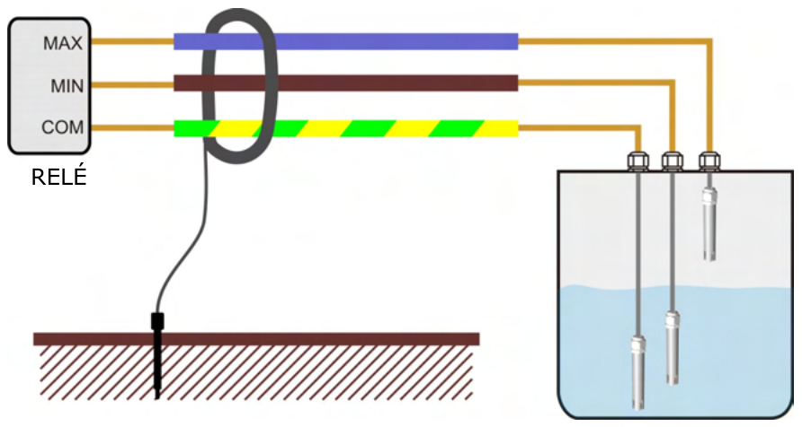
Cables can be crucial for proper operation. It's not essential to always use the highest-quality cable; it must be suitable for the distance, pumping equipment, and electromagnetic interference conditions of the installation. The recommended cross-section depends on the type of cable; the longer the cable, the larger the cross-section.
| Wire | Section | Immunity against electromagnetic disturbances | Connection |
|---|---|---|---|
| Standard | 1..2.5 mm² | Null | Each cable to the corresponding electrode. For installations without special conditions. |
| Screened | 1..1.5 mm² | Moderate | Each wire connects to its corresponding electrode. Connect the shield to ground at one end, preferably on the relay side. If the ground connection is unreliable, it's best not to connect the shield. |
| Braided pair with mesh | 0.52 mm² | Elderly | Connect one wire from each pair to the common electrode. Connect the shield to ground at one end, preferably on the relay side. If the ground is unreliable, it's best to leave the shield unconnected. |
Probe cables and power cables
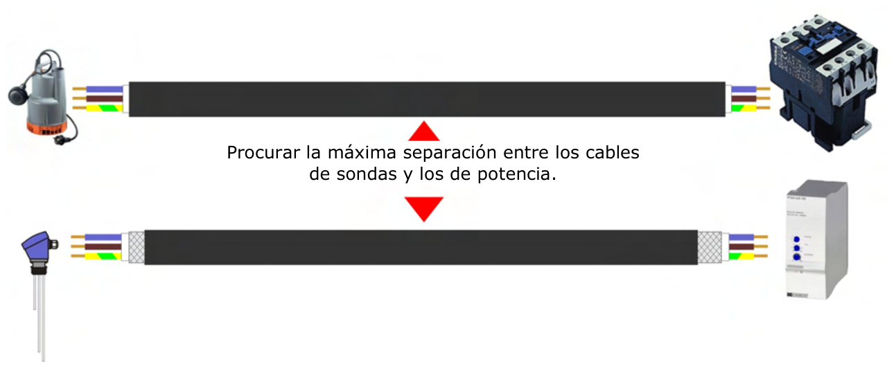
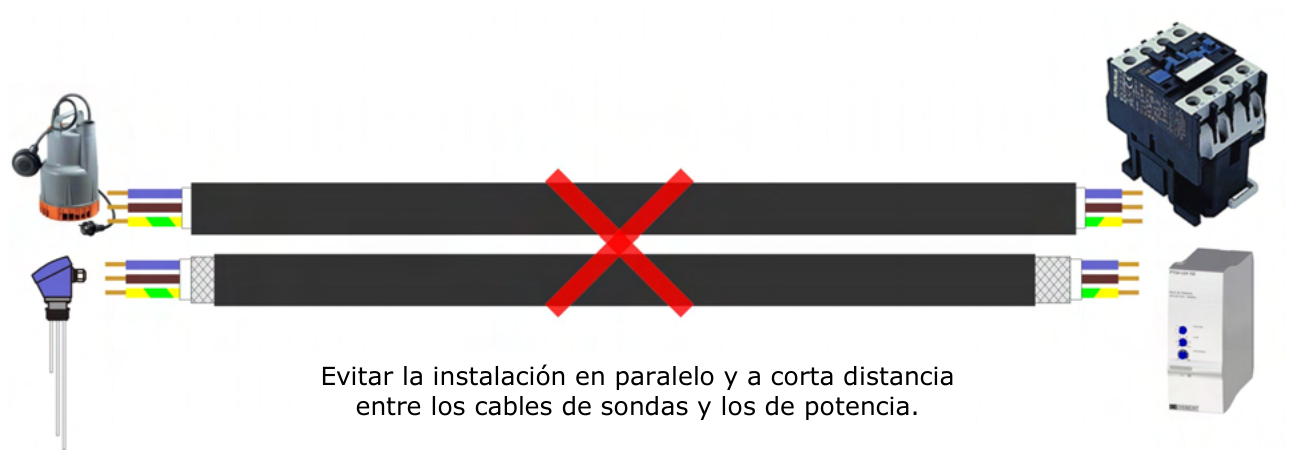
- It is highly advisable that the probe cable not run in parallel with other power or inductive control cables (solenoid valves, motors, etc.).
- If they have to be installed in parallel, the distance between them should be as great as possible.
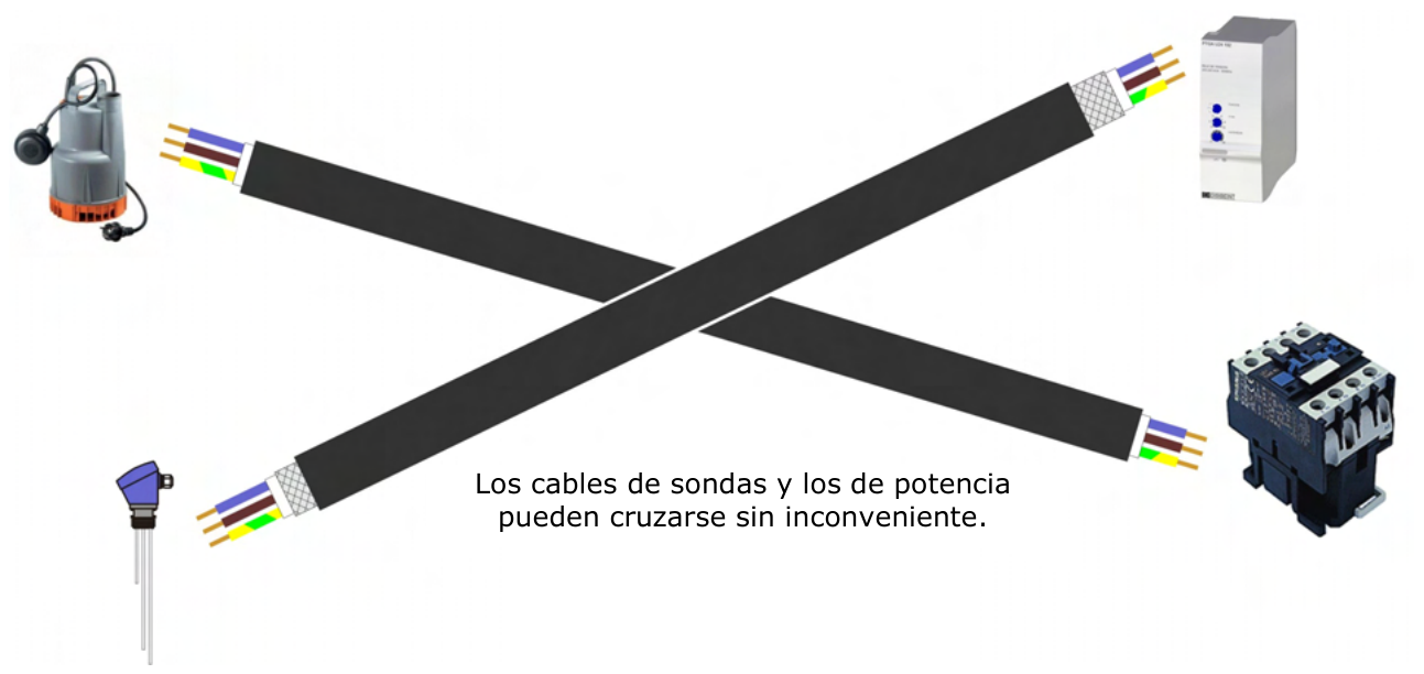
- The probe cable can be crossed with the power cables without any problem.
Maximum distance between probes and relay
The maximum distance between the probes and the relay depends on all the factors mentioned above. It could exceed 1000 meters with optimal operation, or it might not function at a distance of less than 3 meters, so these factors must be taken into account when planning the installation.
Frequently Asked Questions
Where is the common electrode installed?
At the lowest part of the tank or immediately below the electrode that controls the lowest point (minimum level or minimum level alarm), so that it is always in contact with the medium.
Can a metallic deposit be used as a common electrode?
Yes. The medium is always in contact with the tank. It is recommended that the remaining electrodes be as close as possible to the walls.
Which cable offers the most immunity to interference?
The twisted pair with mesh (0.52 mm² cross-section). The shielded version offers moderate immunity, and the standard version offers none.
How is the cable mesh connected?
Connect the electrical ground to one end only, preferably the relay side. If the electrical ground is unreliable, it's best not to connect it.
Can the probe cables run alongside the power cables?
It is advisable to avoid running them in parallel with power or inductive control cables; if this is unavoidable, maintain the maximum possible distance. They can be crossed without any problem.
What is the maximum distance between the probe and the relay?
It depends on the installation factors: it could exceed 1000 meters with optimal operation or not work at a distance of less than 3 meters.
Related
- Water conductivity: principle and applications
- Use of electrical conductivity for measuring nutrients in slurries
- Level sensors
- Liquid level sensors
- Technical guides
- All technical information about GUEMISA
Below, the original PDF document is available for viewing or downloading.