
Technical guide · GUEMISA
For laboratory testing, a passive LVDT with an external conditioner is the best option when resolution, sensor size, or temperature range are important, while an amplified LVDT (with the electronics inside the housing) is preferred when connecting the sensor directly to a standardized 4–20 mA or 0–10 V input is desirable. The stroke length is chosen based on the expected maximum displacement, and linearity is calculated over that stroke: the shorter the stroke, the lower the absolute error.
An LVDT (linear variable differential transformer) measures displacements without electrical contact between the core and the coils, so there is no friction or wear in the measurement.
Operating principle
The sensor has a primary winding and two secondary windings connected in opposition. An oscillator excites the primary winding with alternating current; in Schreiber passive series, for example, the excitation frequency is 10 kHz. Inside the assembly, a ferromagnetic alloy (Ni-Fe) core attached to a stem moves.
- With the core in the center, the voltages of the two secondary windings cancel each other out and the output is zero;
- When the core is displaced, one tension increases and the other decreases; the difference is proportional to the displacement;
- The direction of movement is indicated by the phase of the signal with respect to the excitation.
Since the signal is continuous in space, the resolution of the sensor itself is theoretically infinite; in practice it is limited by noise from the electronics and the acquisition.
Amplified LVDT vs. passive LVDT with conditioner
The difference lies not in the measurement principle, but in where the excitation and demodulation electronics are located.
| Aspect | amplified LVDT | Passive LVDT + conditioner |
|---|---|---|
| Electronics | Integrated into the sensor | External module (DIN rail or OEM) |
| Exit | Normalized: 4…20 mA, 0…20 mA, 0…10 V, ±10 V | Low amplitude AC signal at the sensor; the module outputs 0/4…20 mA, 0…10 V or ±10 V |
| Feeding | Continuous (for example 18…30 VDC or 24 VDC) | Only the conditioning module |
| Wiring between sensor and system | Standardized signal, less sensitive to noise | Short, shielded cable to the module |
| Sensor size | It depends on the model; there are amplified ones from Ø 10 mm (Schreiber SM27) | Very small, from Ø 10 mm in Schreiber SM21 and SM210 |
| Adjustment | According to the model (some series allow scaling the output) | Gain and zero in the module |
| When it fits | Instrumentation and acquisition with standard analog inputs | Limited spaces, extreme temperatures, or multiple sensors with the same air conditioner |
In tests with long cable lengths or electrical noise from motors and drives, amplified current output is usually more convenient. In small test specimens or climate chambers, the passive sensor can be placed inside and the conditioner outside.
Career and linearity
How to choose a career
Choose the standard stroke immediately above the maximum expected displacement, including adjustment positions. An excessively large range reduces sensitivity and, consequently, the useful signal at small deformations; a range that is too small pushes the core to the extremes, where linearity is worse. The data sheets use electrical stroke (the portion over which linearity is guaranteed) and mechanical stroke (the total physical travel): in the FTI 10, for example, 10 mm and 12 mm.
How to read linearity
It is expressed as a percentage of full scale. A 20 mm LVDT with ±0.25% has an error of ±0.05 mm, or ±50 µm; the same percentage on a 5 mm sensor gives ±12.5 µm. Repeatability is usually much lower than linearity error: the FTI 10 reports a typical repeatability of less than 2 µm, and the Schreiber SM224 probe a maximum repeatability of 0.15 µm. For tests comparing measurements, repeatability is more important than absolute linearity.
Resolution
The sensor does not limit the resolution; the conditioner, the analog-to-digital converter, and noise do. Schreiber SM12 series conditioners claim a thermal drift of less than 0.005%/°C and a cutoff frequency of 800 Hz, data that should be considered depending on the test speed.
Spring return or free core
| Configuration | How it works | When is it convenient |
|---|---|---|
| Free core | The core is mechanically attached to the part and moves inside the body without touching the walls. | Dynamic tests or tests with very tight spaces, and where contact force on the sample is not allowed |
| Probe with spring return | The stem is pressed against the workpiece with a defined force | Spot measurements of dimension, thickness or deformation, without attaching the stem to the part |
| Pneumatic return (SM224, option .P) | The force is adjusted by the pressure: 0.4 bar is equivalent to 0.7 N and 1 bar to 2.5 N | When it is necessary to control and reduce the force of contact |
The contact force affects the measurement if the workpiece is soft or thin. According to GUEMISA data, the Schreiber SM224 probe applies approximately 0.7 N at the center of its travel, the Novotechnik FTI 10 LVDT with return requires 4 N with IP50 and 10 N with IP67, and the Novotechnik F200 requires less than 2 N.
Probes and measuring tips
The tip is the part that touches the sample and determines the result. The Schreiber SM22 and SM224 probes have an M2.5 thread at the tip; the F200 is supplied with a threaded probe with a carbide tip and lock nut, allowing it to be attached to the object by friction. If the tip is carbide, wear is reduced on abrasive surfaces. A bellows protects the shaft from dust and splashes (the SM224 is rated IP65 with the bellows). Note that the spring force and the weight of the shaft limit the speed at which the probe follows the surface without losing contact.
Product comparison
| Product | Guy | Career | Linearity | Exit | Protection |
|---|---|---|---|---|---|
| Novotechnik F200 | Amplified, stem | 5, 10 or 20 mm (electrical) | ±0.1 to ±0.3% | ±10 VDC | IP67 with EEM connector |
| Novotechnik FTI 10 | Amplified, with return | 10 mm (electrical) | ±0.1, ±0.2 or ±0.4% | 4…20 mA or 0…20 mA | IP50 or IP67 |
| Schreiber SM21 | Passive | 5 to 20 mm | less than 0.5% (0.25% optional) | AC, with air conditioner | IP66 or IP68 |
| Schreiber SM26 / SM28 | Passive | 24 to 360 mm | less than 0.5% (0.25% optional) | AC, with air conditioner | IP66 with connector, up to IP68 with cable |
| Schreiber SM224 | Passive probe | 2, 5, 10 or 20 mm | less than 0.5% (0.25% optional) | AC, with air conditioner | IP65 with bellows |
| Schreiber SM30 | Amplified | 5, 10 or 15 mm | ±0.5% (±0.25% optional) | 4…20 mA, 0…20 mA, ±10 V, 0…10 V | IP66 with M12 connector, IP68 with cable |
| Schreiber SM41 / SM43 | Amplified and programmable | 20 to 360 mm | 0.2% (up to 0.1% with correction) | 4…20 mA, 0…20 mA, 0…10 V, 0…5 V | IP67, IP68 with cable |
Which GUEMISA products are a good fit?
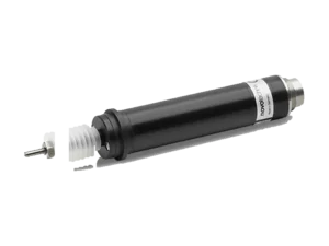 Novotechnik F2005, 10 and 20 mm electrical strokes, ±10 VDC output, ±0.1 to ±0.3% linearity and near infinite resolution.View technical specifications →
 Novotechnik FTI 1010 mm electrical stroke, 4…20 mA or 0…20 mA output, typical repeatability less than 2 µm and IP50 or IP67.View technical specifications →
 Schreiber SM26 and SM28Passive LVDT from 24 to 360 mm, free core or spring-loaded probe; combines with the SM10 and SM12 series conditioners.View technical specifications →
 Schreiber SM224probe from 2 to 20 mm with maximum repeatability of 0.15 µm and pneumatic drive option.View technical specifications →
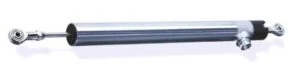 Schreiber SM41 and SM43LVDT amplified from 20 to 360 mm, stainless steel housing Ø 25 mm, scalable output.View technical specifications →
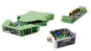 Schreiber SM12DIN rail conditioner with 0/4…20 mA, 0…10 V or ±10 V outputs for passive LVDTs.View technical specifications →
Documentation and related cases
- LVDT: What it is and how it works (PDF)
- Schreiber Messtechnik LVDT Sensor Catalog (PDF)
- All technical information about GUEMISA
Frequently Asked Questions
What is the difference between an amplified and a passive LVDT?
The amplified sensor houses the excitation and demodulation electronics and delivers 4–20 mA or a standardized voltage. The passive sensor delivers an alternating signal and requires an external signal conditioner.
How accurate is an LVDT?
It depends on the model. In GUEMISA's data sheets, linearity ranges from ±0.1% in the F200 and FTI 10 to less than 0.5% in standard liabilities, and always refers to the full scale of the career.
Can I use a passive LVDT with a PLC?
Yes, but it needs a conditioner between the two that converts the alternating signal to 4…20 mA or 0…10 V, such as the Schreiber SM12 modules.
When do I choose free core and when do I choose probe?
The free core is used when the stem can be attached to the workpiece and contact force is not required. The spring-loaded probe is used for measuring without fixing the stem, in exchange for a contact force of between 0.7 N and 10 N depending on the model.
Does an LVDT suffer wear and tear?
The core does not touch the coils, so the measurement does not cause internal wear. In probes, wear is concentrated at the tip and in the stem guide.
Send us the application, race or reference you have and we will tell you the model and your order code.