TP1 IO-Link profile magnetostrictive transducer
- Manufacturer: Novotechnik
- Category: Displacement, SENSORS, Magnetostrictive Linear Transducer, Linear Transducers
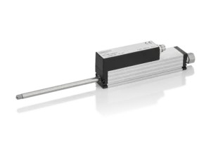
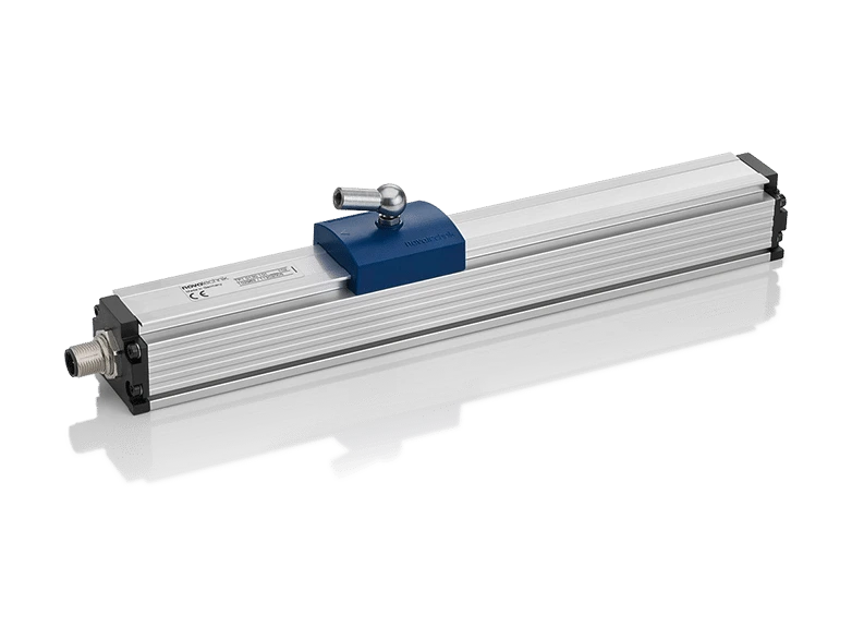
Novotechnik TP1 IO-Link magnetostrictive transducer. NOVOSTRICTIVE technology, contactless.
Profile magnetostrictive transducer for non-contact linear position measurement. Stroke from 50 to 4250 mm. IP67/IP68 protection. Floating or guided position marker. Up to three positions can be measured, or up to two positions with their velocity, one per position marker.
Key points
- Unlimited mechanical life
- Resolution down to 1 µm, independent of length
- Temperature coefficient ≤ 15 ppm/K
- Shock 100 g (11 ms); vibration 20 g
- IP67 / IP68 protection
- Same series with analog, SSI, pulse, incremental, CANopen and IO-Link interfaces: see their datasheets
Technical Frequently Asked Questions
What can be connected to the TP1 IO-Link magnetostrictive transducer?
It can be connected to Novotechnik M12 connectors and cables, Novotechnik M16 connectors and cables, Novotechnik linear sensor couplings and fixings, and Novotechnik linear sensor positioners (magnets and cursors).
How do I order the TP1 IO-Link magnetostrictive transducer?
The order code has 5 fields: stroke (mm), mechanical version, interface, parameters, and connection. For example, TP1-0800-101-A11-107 is the version with an 800 mm electrical range, profile design, IO-Link, 5 µm resolution with 1 x position and 1 fixed marker, and a 4-pin M12x1 connector. All the options for each field are available in the order code configurator on this page.
Under what conditions does the TP1 IO-Link magnetostrictive transducer operate?
Operating temperature: -40 … +85 °C. Protection: IP67.
Properties
| Feature | Specification |
|---|---|
| Description | |
| Housing | Anodized aluminum AlMgSi0.5 F22, 3.3206.71 |
| End flanges | Aluminum G AlSi12Cu1 (FE) |
| Mounting | Adjustable cable ties (included) |
| Placeholder | Floating, made of plastic; or guided, made of plastic, with articulated coupling |
| Electrical connection | M12x1 4-pole connector |
| Electronics | SMD with integrated ASIC; the connector housing (display) is bonded to the sensor housing; the housing is capacitively decoupled from the electronics |
| Electrical data | |
| Measured variables | Position, speed, and temperature |
| Electrical range (dimension B) | 0050 … 4250 mm |
| Number of placeholders | 1 to 3 |
| Protocol | IO-Link Spec V1.1 according to IEC 61131-9 |
| Profile | Smart Sensor Profile (compatible with V1.0) |
| Programmable parameters | Zero point shift, resolution, averaging |
| Configurability | Number of position markers and measured variables (position, speed); all versions of the order specifications (e.g., 1 x position) can also be configured by the customer (e.g., to 2 x position and 2 x speed) |
| Transfer speed | COM 3 (230.4 kB) |
| Type of plot | 2,2 |
| Minimum cycle time | 1 ms |
| Update frequency | 1 kHz (internal sampling frequency < 750 mm: 2 kHz; 750 … < 2000 mm: 1 kHz; > 2000 mm: 0.5 kHz) |
| Position resolution | 1 or 5 µm |
| Speed resolution | 0.1 or 0.5 mm/s |
| Reproducibility (rounded to the resolution) | ≤ 6 µm |
| Hysteresis (rounded to the resolution) | ≤ 4 µm |
| Absolute linearity (*), length < 250 mm | ≤ ±25 µm |
| Absolute linearity (*), length < 750 mm | ≤ ±30 µm |
| Absolute linearity (*), length < 1000 mm | ≤ ±50 µm |
| Absolute linearity (*), length < 2500 mm | ≤ ±80 µm |
| Absolute linearity (*), length up to 4250 mm | ≤ ±120 µm |
| Zero point tolerance | ±0.5 mm |
| Temperature error | ≤ 15 ppm/K (min. 0.01 mm/K) |
| Supply voltage | 24 (18 … 30) VDC |
| Power supply voltage ripple | max. 10 % Ub |
| Current consumption (no load) | ≤ 100 mA |
| Reverse polarity protection | Yes, up to the maximum supply voltage. |
| Short circuit protection | Yes (C/Q versus GND and the supply voltage) |
| Overvoltage protection | 36 VDC (permanent) |
| Insulation resistance (500 VDC) | ≥ 10 MΩ |
| IO-Link interface: process data, parameters, and events | |
| Vendor ID | 0x030B (779) |
| M-sequence capability | 0x2B; preoperateType_1_V; operateType_2_V; ISDU supported |
| Process data cycle | Master V1.0: 2 x 1 ms = 2 ms; Master V1.1: Master cycle = 1 ms |
| Process data format | Signed integer; e.g. 32 bits = position, or 48 bits = 32 position bits + 16 speed bits |
| Null point offset | 32-bit signed value, added to the factory zero point (max.: sensor length); can be adjusted without a placeholder |
| Valid process data | 0xF000 FF10 … 0x7FFF FFF0 (PD Valid) |
| Error value (without marker) | 0x7FFF FFFC; invalid data (PD Invalid Bit) |
| Device ID, 1 x position | 0x00044C (001100); 4 bytes |
| Device ID, 1 x position + speed | 0x000456 (001110); 6 bytes |
| Device ID, 2 x position | 0x0004B0 (001200); 8 bytes |
| Device ID, 2 x position + 2 x speed | 0x0004C4 (001220); 12 bytes |
| Device ID, 3 x position | 0x000514 (001300); 12 bytes |
| Resolution (parameter) | 0 = 1 µm; 1 = 5 µm; from 1 to 5 µm, the speed goes from 0.1 to 0.5 mm/s |
| IO-Link interface: process data, parameters, and events | |
| Average (parameter) | 0 = no moving average; 1 … 5 = moving average of 2 / 4 / 8 / 16 / 32 values |
| Mode (parameter) | 0 = 1 x position; 1 = 1 x position + velocity; 2 = 2 x position; 3 = 2 x position + 2 x velocity; 4 = 3 x position |
| Change in operation | Averaging and resolution: Yes (data invalid until 10 ms later); Mode: Effective after disconnecting and connecting the power |
| Reading parameters | Position 1 to 3 (32 bit), speed 1 and 2 (16 bit), chip temperature in °C (16 bit), measurement range, measurement resolution 1 µm |
| Warning 0x8C10 and 0x8C30 | Placeholder below or above the defined working range |
| Error 0x8C20 | The placeholder is missing. |
| Error 0x4210 | Internal temperature exceeded |
| Error 0x5000 | Internal system failure |
| Error 0x8CA0 | Storage failure |
| Parameters | Stored in non-volatile memory |
| Factory reset | Command 0x80 at index 0x0002, subscript 0 |
| IODD Files | Available on the manufacturer's website |
| Dimensional plane | |
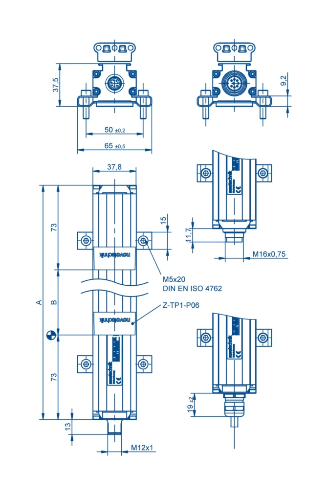
| Electrical range (dimension B) | 0050 … 0500 mm in 25 mm increments; 500 … 1000 mm in 50 mm increments; 1000 … 2000 mm in 100 mm increments; 2000 … 4250 mm in 250 mm increments; other lengths available upon request |
| Housing length (dimension A) | dimension B + 146 mm |
| Maximum operating speed with valid output signal | 10 m/s |
| Maximum operating acceleration with valid output signal | 200 m/s² |
| IEC 60068-2-27 Shock | 100 g (11 ms), one stroke |
| Vibration IEC 60068-2-6 | 20 g (5 … 2000 Hz, Amax = 0.75 mm) |
| DIN EN 60529 protection, with fixed connector | IP67 |
| DIN EN 60529 protection, with cable | IP68 |
| Life | Mechanically unlimited (with floating placeholder) |
| Working temperature | -40 … +85 °C |
| Storage temperature | -40 … +105 °C |
| Working humidity | 0 … 95 % HR (non-condensing) |
| Safety and compliance | |
| MTTF (IEC 60050) | 322 years |
| Accordance | EC |
| Electromagnetic compatibility | |
| EN 61000-4-2 | Electrostatic discharges (ESD) 4 kV, 8 kV |
| EN 61000-4-3 | Electromagnetic fields 10 V/m |
| EN 61000-4-4 | Fast transients (burst) 1 kV |
| EN 61000-4-6 | Conducted disturbances induced by RF fields 10 V rms. |
| EN 55016-2-3 | Radiated noise emission, class B |
| Option | Meaning |
|---|---|
| Example: TP1-0800-101-A11-107 = 800 mm electrical range, profile design, IO-Link, 5 µm resolution with 1 x position and 1 fixed marker and 4-pole M12x1 connector. | |
| 1. Electrical range (mm) | |
| 0050 … 4250 | Steps from 25 mm to 500, from 50 mm to 1000, from 100 mm to 2000 and from 250 mm to 4250; other lengths available upon request |
| 2 · Mechanical version | |
| 101 | Profile design |
| 3 · Electrical interface | |
| TO | IO-Link |
| 4 · Interface parameters (A__) | |
| 11 | Resolution 5 µm, 1 x position, 1 fixed marker |
| 12 | Resolution 5 µm, 1 x position and velocity, 1 fixed marker |
| 13 | Resolution 5 µm, 2 x position, 2 fixed markers (from 150 mm) |
| 14 | 5 µm resolution, 2 x position and speed, 2 fixed markers (from 150 mm) |
| 15 | Resolution 5 µm, 3 x position, 3 fixed markers (from 250 mm) |
| 31 | Resolution 1 µm, 1 x position, 1 fixed marker |
| 32 | Resolution 1 µm, 1 x position and velocity, 1 fixed marker |
| 33 | Resolution 1 µm, 2 x position, 2 fixed markers (from 150 mm) |
| 34 | Resolution 1 µm, 2 x position and speed, 2 fixed markers (from 150 mm) |
| 35 | Resolution 1 µm, 3 x position, 3 fixed markers (from 250 mm) |
| 5 · Electrical connection | |
| 107 | M12x1 connector, 4 poles |
| The code is formed using one option from each field, in the order shown in the example. Contact us and we will confirm the exact reference. | |
Related documentation, cases, and guides
Technical documentation
- Novotechnik General Catalogue: Linear and Angular Position Sensors
- Technical definitions of potentiometers: linearity, RGV and hysteresis
- Novotechnik position sensors with IO-Link interface
- Position sensors for valves and actuators: Novotechnik series
- Novotechnik linear and rotary sensors for automotive applications
Other products