























How a position encoder works
A encoder It is a sensor that transforms a mechanical movement into an electrical signal that can be interpreted by a PLC, a frequency converter, a servo controller, a counter, a data acquisition system, or an industrial computer.
It is also called position encoder, although in the current industrial environment the term encoder.
Depending on its design, an encoder can provide information about:
- The angular position of an axis.
- The linear position of a moving element.
- The displacement made.
- The direction of movement.
- The speed of rotation or displacement.
- The number of laps completed.
- Acceleration, calculated from the change in speed.
Understanding how an encoder works allows you to correctly select its technology, resolution, output interface, and mounting system.
Encoders are fundamental components in industrial automation, robotics, CNC machines, servomotors, elevators, cranes, wind turbines, production lines, packaging machinery, printing systems, and measuring equipment.
In simple terms, an encoder is the device that allows a machine to know how much an axis has moved, in what direction it has moved, and, in certain models, its exact position.
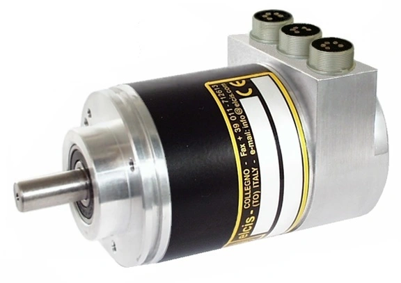
How does an encoder work?
The general operating principle of an encoder consists of displacing a physical pattern attached to the element whose position is to be measured.
In a rotary encoder, This pattern is typically found on a disk attached to the shaft. In a linear encoder, It is placed on a ruler, a tape, or a scale that moves longitudinally.
The pattern contains distinct zones that can be detected by a fixed read head. Depending on the technology used, these zones can be distinguished by their properties:
- Opticians.
- Magnetic.
- Inductive.
- Capacitive.
- Electrical or contact.
As the disk or ruler moves, the head detects successive changes in the pattern. The internal electronics condition these signals and convert them into pulses, sinusoidal signals, or digital words that represent the movement or position.
The system does not necessarily measure position through direct contact. In most modern industrial encoders, the reading is taken without contact, which reduces wear and allows for a long service life.
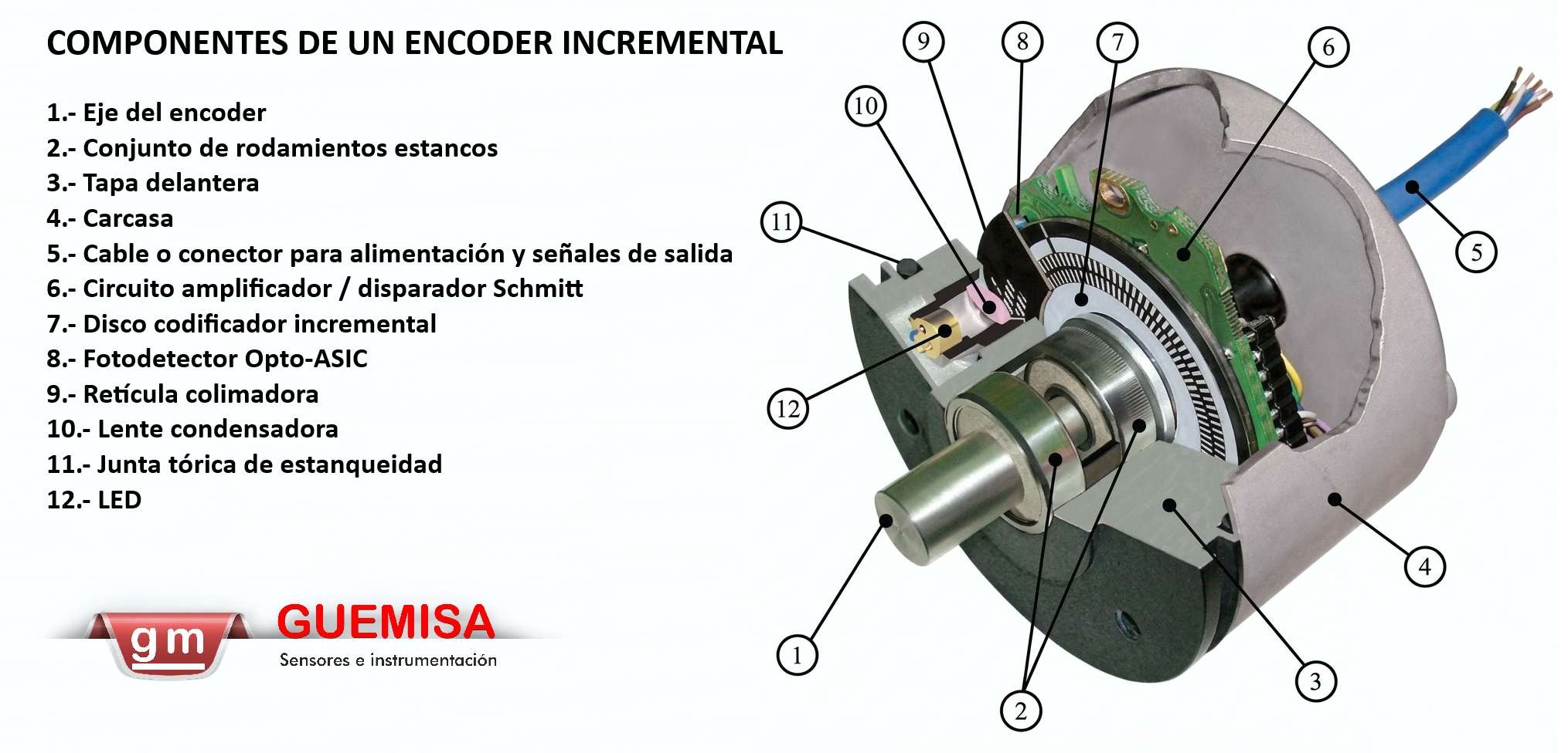
What does an encoder measure?
The quantity that an encoder directly measures is the position or the displacement. However, other variables related to movement can also be calculated from its signal.
Position
Position can be angular, usually expressed in degrees, revolutions or counts, or linear, expressed in millimeters, micrometers or other units of length.
Displacement
In an incremental encoder, the displacement is obtained by counting the pulses generated during the movement.
Speed
Speed is determined by measuring the frequency of the pulses or the time elapsed between two consecutive pulses.
Direction of movement
The direction is determined by comparing two signals that are out of phase with each other, usually called channels A and B.
Acceleration
Acceleration can be calculated from the change in velocity over time. It is not a direct output from the encoder, but a value calculated by the control system.
Rotary encoder and linear encoder
Encoders can be classified according to the type of movement they are designed to measure.
Rotary encoder
A rotary encoder It measures the rotation of a shaft. The measuring element is usually a disk attached to the shaft and divided into coded sectors or tracks.
It allows you to know:
- The angle turned.
- The angular position.
- The rotation speed.
- The direction of rotation.
- The number of revolutions.
It is the most common type of encoder in motors, servomotors, gearboxes, robots, CNC machines, elevators and positioning systems.
Linear encoder
A linear encoder It measures the displacement of an element along a straight path.
Instead of a disk, use a ruler, an optical scale, a magnetic tape, or a linear pattern. The read head moves relative to this scale, or the scale moves relative to the head.
It is mainly used in:
- Machine tools.
- Positioning tables.
- Dimensional metrology equipment.
- Linear cylinders and actuators.
- Cutting systems.
- Printers and graphic machinery.
- High-precision positioning applications.
| Feature | Rotary encoder | Linear encoder |
|---|---|---|
| Measured movement | Rotation of an axis | Rectilinear displacement |
| Encoded element | Disc or ring | Ruler, tape measure or scale |
| Usual unit | Degrees, turns, or counts per revolution | Millimeters, micrometers, or pulses per unit of length |
| Applications | Motors, servomotors, robots and gearboxes | Machine tools, actuators and metrology |
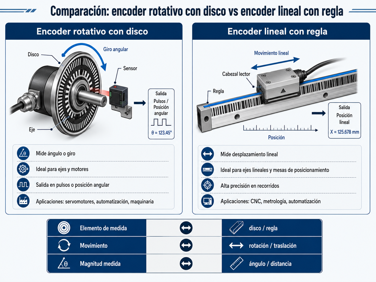
Incremental encoder: operation and signals
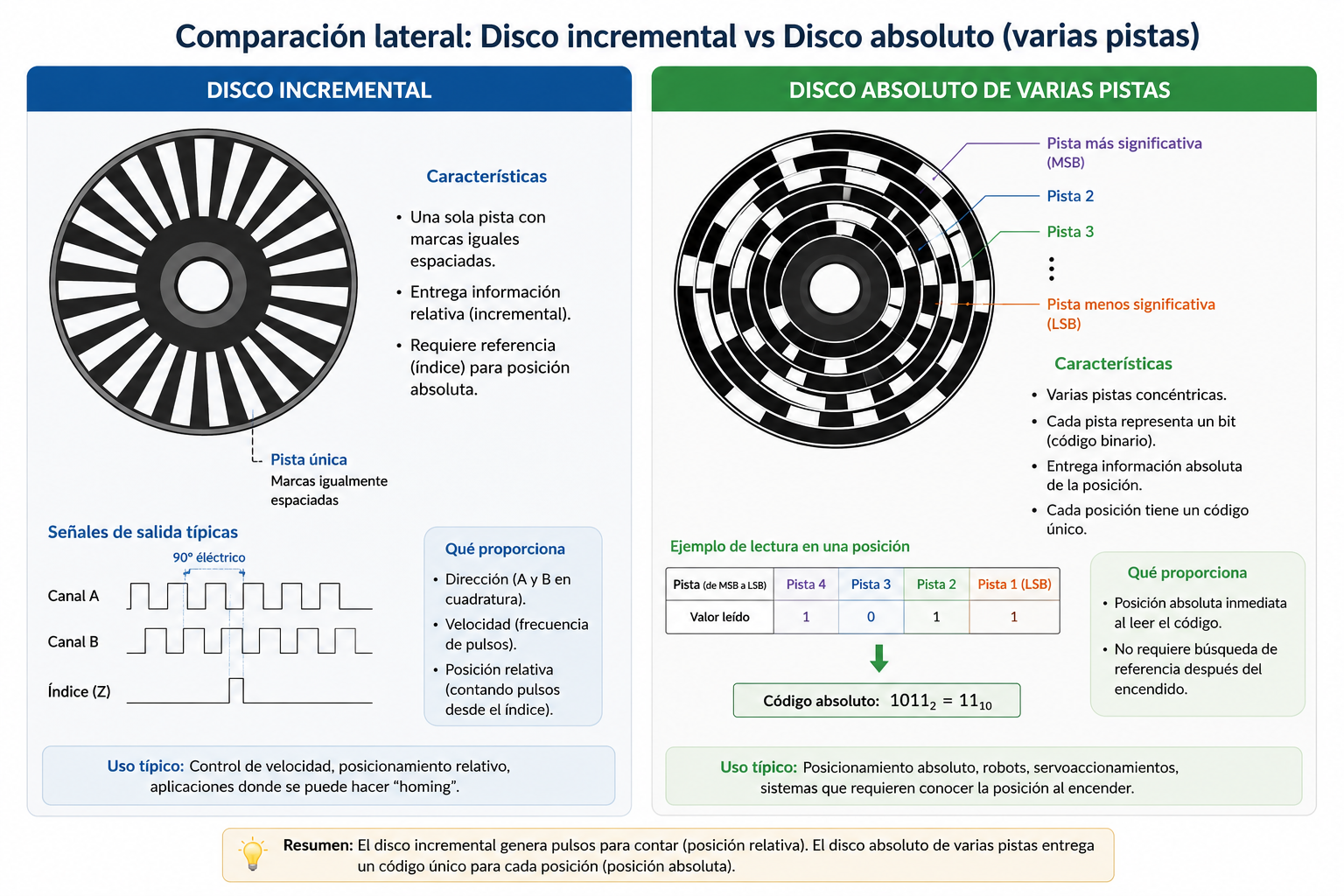
A incremental encoder It generates pulses as movement occurs. Each pulse represents a certain increment of position, but does not by itself identify an absolute position.
The position is calculated by counting the impulses from a known starting point.
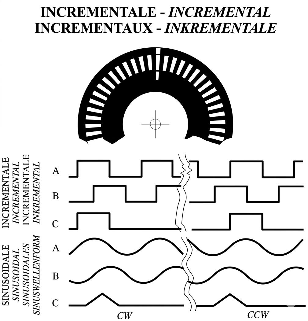
In an incremental optical encoder, the disk contains transparent and opaque sectors distributed evenly. A light source is located on one side of the disk and a photodetector on the opposite side.
When the disc rotates, the following sequence occurs:
- A transparent area allows light to reach the detector.
- An opaque area interrupts the light beam.
- The photodetector switches between two electrical levels.
- The electronics condition the signal.
- The output becomes a train of impulses.
- The controller counts the pulses to calculate the displacement.
The number of pulses generated per revolution depends on the resolution of the encoded disk.
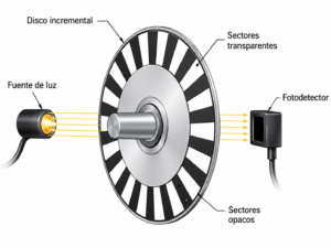
Channels A and B of an incremental encoder
A single-signal encoder can count pulses, but it cannot directly determine the direction of movement. The same type of pulse is generated whether the shaft rotates clockwise or counterclockwise.
To solve this problem, most industrial incremental encoders incorporate two signals called Channel A and Channel B.
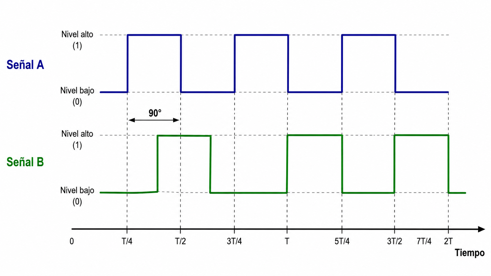
Both signals have the same frequency, but are electrically out of phase by 90°, that is, a quarter of a cycle. This arrangement is called quadrature.
The controller determines the direction by observing which of the two signals changes first:
- If channel A moves ahead of channel B, the shaft rotates in one direction.
- If channel B moves ahead of channel A, the shaft rotates in the opposite direction.
The specific direction assigned to each sequence will depend on the mechanical assembly, the side from which the axis is viewed, and the configuration of the control system.
The use of two out-of-phase signals allows a bidirectional counter to add pulses in one direction and subtract them when the movement changes direction.
Z channel, index or reference
In addition to channels A and B, many incremental encoders incorporate a third signal called:
- Channel Z.
- Index.
- Zero momentum.
- Reference pulse.
- Marker pulse.
The Z channel typically generates a single pulse per revolution. Its purpose is to provide a repetitive angular reference.
This signal is used for:
- Perform a machine origin search.
- Synchronize the counter.
- Verify that a revolution has been completed.
- Correct any accumulated deviations.
- Establish a mechanical reference position.
The Z channel does not convert the incremental encoder at all. It only provides a known mark once per revolution. Until the axis reaches that mark, the system does not know its reference position.
What happens if an incremental encoder is disconnected?
The incremental encoder does not intrinsically store the position. It generates information about the movement, but the accumulated position is obtained externally using a counter.
If the power supply is interrupted and the controller loses the counted value, the position becomes unknown. When the machine is restarted, a referencing operation is usually required. homing.
A positioning error can also occur if:
- An impulse is lost due to interference.
- The optical disc is contaminated.
- There is a break in the cable.
- The output frequency exceeds the counter's capacity.
- The axis moves while the reading system is disconnected.
In critical systems, counters with non-volatile memory, backup power supplies, or periodic reference routines can be used. These measures belong to the control system and do not convert the incremental measurement into an absolute measurement.
Absolute encoder: how it works
A absolute encoder It provides a unique value for each position in its path.
Instead of simply generating a sequence of pulses, it delivers a digital word that directly represents the position of the axis or the rule with respect to an internal reference.
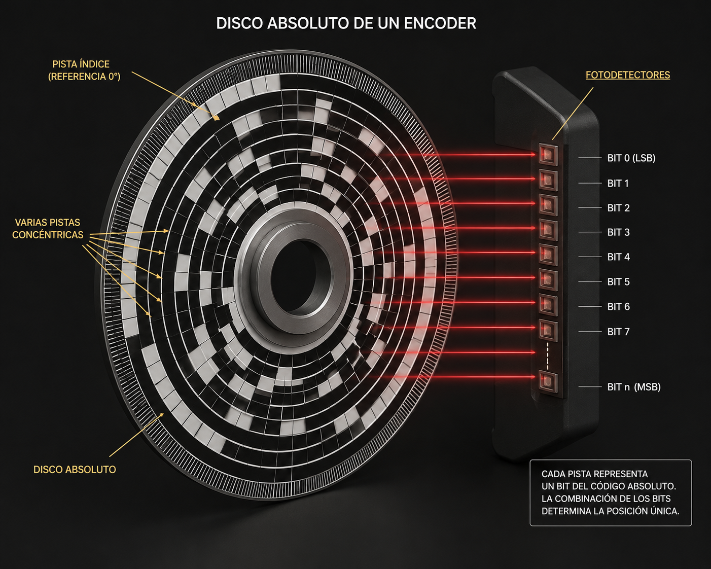
In an absolute optical encoder, the disc incorporates several concentric tracks. Each track represents a bit and contains transparent and opaque sectors distributed according to a specific code.
An array of photodetectors simultaneously reads all the tracks. The combination of detected states forms a different digital word for each position.
The number of available positions is calculated using:
Where n is the number of bits of the encoder.
| Resolution | Positions per lap | Theoretical angular increment |
|---|---|---|
| 8 bits | 256 | 1,4063° |
| 10 bits | 1.024 | 0,3516° |
| 12 bits | 4.096 | 0,0879° |
| 14 bits | 16.384 | 0,0220° |
| 16 bits | 65.536 | 0,00549° |
| 18 bits | 262.144 | 0,00137° |
| 20 bits | 1.048.576 | 0,000343° |
The theoretical angular resolution can be calculated using:
For example, a 12-bit absolute encoder divides a complete revolution into 4,096 positions:
Does an absolute encoder retain its position without power?
An absolute encoder doesn't need to count all the movements made from a given origin to determine its position. When it's fed, it reads the code corresponding to the current position and immediately outputs that value.
This means that, even if it has been disconnected, it can regain its angular position as soon as it receives power again.
However, it is necessary to differentiate between single-turn and multi-turn absolute encoders.
Singleturn or singleturn absolute encoder
An absolute encoder singleturn determines the exact position within a revolution.
For example, a 12-bit singleturn encoder can distinguish 4,096 positions within 360°, but it does not indicate how many complete turns have been made.
Multiturn or multiturn absolute encoder
An absolute encoder multiturn It determines the position within a revolution and also counts the number of revolutions made.
The multiturn register can be obtained by:
- Internal gears.
- Electronic meters with battery.
- Energy harvesting systems.
- Magnetic or electronic technologies without batteries.
A multiturn encoder is suitable when the shaft can make several turns and it is necessary to maintain the overall position, as in cranes, elevators, spindles, valves, robots, and automatic storage systems.
Why do absolute encoders use Gray code?
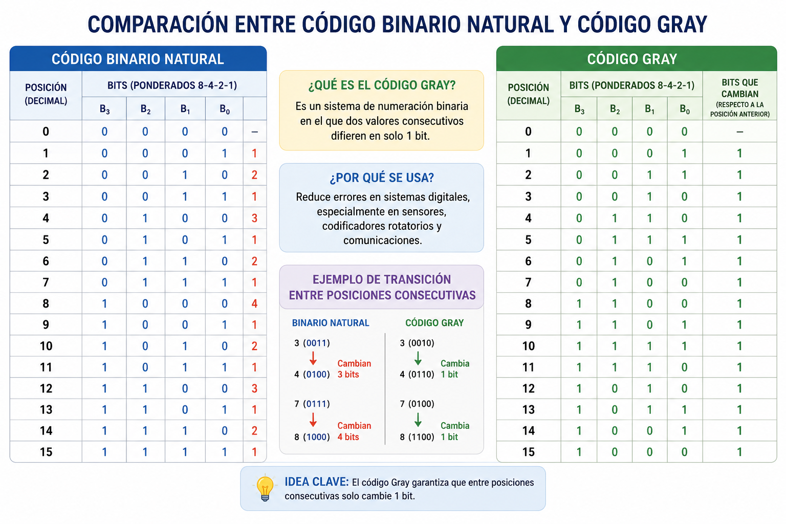
In an absolute disk encoded in natural binary, several bits can change simultaneously when moving from one position to the next.
For example:
| Position | Binary code |
|---|---|
| 3 | 0011 |
| 4 | 0100 |
During this transition, three bits change. Since the sensors do not switch at exactly the same instant, an incorrect intermediate combination could be obtained for a fraction of a second.
He Gray Code This reduces this ambiguity because only one bit changes between two consecutive positions.
Its main advantage in an absolute encoder is to reduce errors associated with the transition between adjacent positions.
Gray code is not, in itself, a transmission error detection code. To transmit position data over an industrial cable, protocols incorporating additional checks can be used.
Difference between incremental and absolute encoders
The fundamental difference lies in the type of information that each encoder provides.
| Feature | Incremental encoder | Absolute encoder |
|---|---|---|
| Information generated | Displacement impulses | Digital position value |
| Position when turning on | A reference point must be established. | It is obtained immediately |
| You need an external accountant | Yeah | Not to know the current position |
| Loss of position due to power outage | It can happen | Not within its absolute range |
| Sense detection | Through channels A and B | From successive positions or by means of the protocol |
| Reference | Optional Z-channel | Internal reference |
| Complexity | Minor | Elderly |
| Usual cost | Smaller | Higher |
| Typical application | Speed and relative positioning | Direct positioning |
| Common signs | A, B and Z | SSI, BiSS, CANopen or industrial bus |
When should you choose an incremental encoder?
An incremental encoder is a suitable solution when:
- A reference routine is available.
- Speed needs to be measured primarily.
- Cost is an important factor.
- The system can store the counter externally.
- There is no risk of movement with the machine disconnected.
When should you choose an absolute encoder?
An absolute encoder is preferable when:
- The position must be known immediately upon starting.
- It is not possible to perform a source search.
- The axis can be moved while the equipment is turned off.
- An incorrect position can cause damage.
- The total number of turns needs to be known.
How an optical encoder works
Optical technology is one of the most widely used when good resolution, accuracy, and repeatability are required.
An optical encoder is typically made up of the following elements:
- A shaft or moving element.
- A coded disk or scale.
- A light source, usually an LED.
- An optical system or collimating lens.
- One or more photodetectors.
- A conditioning circuit.
- An output stage or communication interface.
Light source
The light source illuminates the encoded pattern. An LED is typically used due to its small size, fast response time, and long lifespan.
The system can incorporate a lens to direct the radiation onto the disk and obtain a well-defined beam.
Optical disc or scale
The coded element can be manufactured in:
- Glass.
- Metal.
- Plastic material.
- Flexible film.
- Precision rule.
Glass allows for very stable and defined patterns, but it can be more susceptible to impacts. Metal discs offer greater mechanical resistance, although their manufacturing process and flatness can limit the achievable resolution.
Photodetector
The photodetector converts the received light into an electrical signal. A photodiode, a phototransistor, or a photoarray can be used.
The original detector signal is not always perfectly square. It can have an approximately sinusoidal shape due to the beam size, slit geometry, and optical system response.
The internal electronics amplify, filter, and compare the signal to obtain correctly defined output levels.
Conditioning electronics
The encoder electronics can perform functions such as:
- Photodetector signal amplification.
- Compensation for intensity variations.
- Comparison using thresholds.
- Generation of square waves.
- Interpolation of sinusoidal signals.
- Error correction.
- Gray code conversion.
- Communication with the control system.
Transmissive optical encoder
In a transmissive optical encoder, the light source and the detector are located on opposite sides of the disk.
The transparent areas allow light to pass through, while the opaque areas block it. This is a common configuration in precision rotary encoders.
Reflective optical encoder
In a reflective optical encoder, the light source and the detector are located on the same side.
The disc or scale has reflective and non-reflective areas. The amount of light reflected changes with position, allowing movement to be detected.
| Feature | Transmissive optical | Reflective optic |
|---|---|---|
| Position of the sender and receiver | On opposite sides | On the same side |
| Pattern used | Transparent and opaque areas | Reflective and non-reflective areas |
| Detection | Transmitted light | Reflected light |
Optical encoders based on Moiré fringes
High-resolution optical encoders can use two superimposed gratings or scales. When one moves relative to the other, interference fringes appear, known as Moiré stripes.
A small shift in the scale produces a more visible movement of the observed stripes. This allows for the detection of very small displacements and the interpolation of positions between the physical divisions of the pattern.
This technique can be applied to both linear and rotary encoders.
Advantages of the optical encoder
- High resolution.
- Good accuracy.
- Excellent repeatability.
- Absence of mechanical contact.
- Low hysteresis.
- Ability to generate incremental or absolute signals.
- Possibility of interpolation.
- Good response at high speeds.
Limitations of the optical encoder
The quality of the measurement may be affected by:
- Dust.
- Oil.
- Smoke.
- Condensation.
- Internal humidity.
- Optical misalignment.
- Vibrations or impacts.
- Disc deterioration.
- Excessive temperature variations.
- Degradation of optoelectronic elements.
These limitations do not mean that an optical encoder cannot be used in industry. Modern industrial models incorporate sealed housings, bearings, protected optics, electronic compensation, and appropriate protection ratings.
The selection should be made according to the actual installation environment.
Other encoder technologies
Although optical technology is one of the best known, there are other measurement principles suitable for specific environmental conditions or requirements.
Magnetic encoder
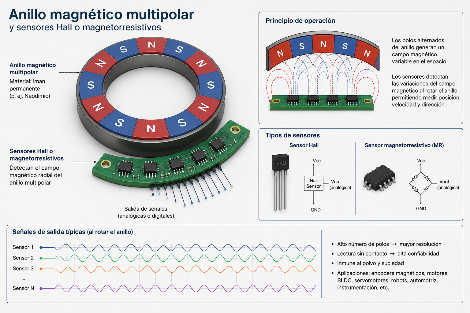
A magnetic encoder It uses a magnet, a ferromagnetic gear, or a ring with alternating magnetic poles.
The magnetic field can be detected by:
- Hall effect sensors.
- Magnetoresistive sensors.
- Anisotropic magnetoresistive sensors.
- Tunnel effect magnetoresistive sensors.
- Inductive coils.
- Wiegand effect sensors.
The orientation or intensity of the field changes as the axis rotates. The electronics process the resulting signals to calculate the angle or generate incremental pulses.
Its main advantages are:
- Good resistance to dust and oil.
- Vibration tolerance.
- Compact construction.
- Contactless operation.
- Adaptation to mobile machinery and industrial environments.
Among its limitations are the possible influence of external magnetic fields, the need to control the distance between the magnet and the sensor, and, in some designs, a lower accuracy than that of an equivalent optical encoder.
Inductive encoder
A inductive encoder It generates an electromagnetic field using coils. The displacement of a conductive piece or pattern modifies the coupling, inductance, or induced currents.
The electronics measure these variations and determine the position.
Its main characteristics are:
- Contactless operation.
- Good resistance to dirt, moisture and vibrations.
- Absence of optical elements.
- Suitable for demanding industrial applications.
- Good mechanical stability.
An inductive encoder should not be confused with a resolver, although both use electromagnetic phenomena to measure an angular position.
Capacitive encoder
A capacitive encoder It has fixed and moving electrodes. The movement periodically modifies the electrical capacitance between them.
The electronics measure these variations and calculate the position.
Its key features include:
- Low consumption.
- Compact construction.
- Good resolution.
- Immunity to magnetic fields.
Humidity, distance variations, dielectric contamination, and parasitic capacitances must be controlled through proper design and sealing.
Mechanical or contact encoder
In a mechanical encoder, brushes move over conductive and insulating sectors.
Its main advantage is that it can generate high amplitude electrical signals without the need for a complex optical system.
However, it has significant limitations:
- Mechanical wear.
- Rebound of contacts.
- Speed limit.
- Shorter lifespan.
- Possible loss of contact due to vibration.
For this reason it is mainly used in panel controls, selectors and low-speed applications, and much less so in precision industrial positioning.
Comparison of encoder technologies
| Technology | Beginning of reading | Advantages | Limitations | Common applications |
|---|---|---|---|---|
| Optics | Interruption or reflection of light | High resolution, accuracy and repeatability | Sensitive to contamination and condensation if not properly protected | CNC, robotics, servomotors and metrology |
| Magnetic | Reading a magnetic field | Robustness against dust, oil and vibrations | Possible influence of external fields and mounting distance | Mobile machinery, motors and industrial environments |
| Inductive | Electromagnetic coupling variation | High environmental resistance and contactless operation | More complex electronics | Heavy industry and demanding applications |
| Capacitive | Variation in electrical capacity | Low consumption and compact design | Influence of humidity and parasitic capacities | Compact instrumentation and equipment |
| Mechanics | Contacts regarding driving sectors | Simplicity and low cost | Wear and tear, rebounds, and limited speed | Panel controls and selectors |
Resolution of an incremental encoder
In rotary incremental encoders, the resolution is usually expressed by:
- PPR: pulses per revolution.
- Impulses per lap.
- Lines per lap.
- CPR: accounts per revolution.
The definition used by the manufacturer should always be checked, because the terms PPR and CPR are not used in the same way in all catalogs.
In an encoder with signals A and B, the controller can count:
- One edge per period: decoding ×1.
- Two edges per period: ×2 decoding.
- The four flanks of A and B: ×4 decoding.
For example, a 1.024 PPR encoder can provide up to 4.096 counts per revolution when reading all four edges of signals A and B.
The increase in the number of counts should not be confused with a corresponding improvement in accuracy. Digital resolution and mechanical precision are different specifications.
Resolution, accuracy, and repeatability
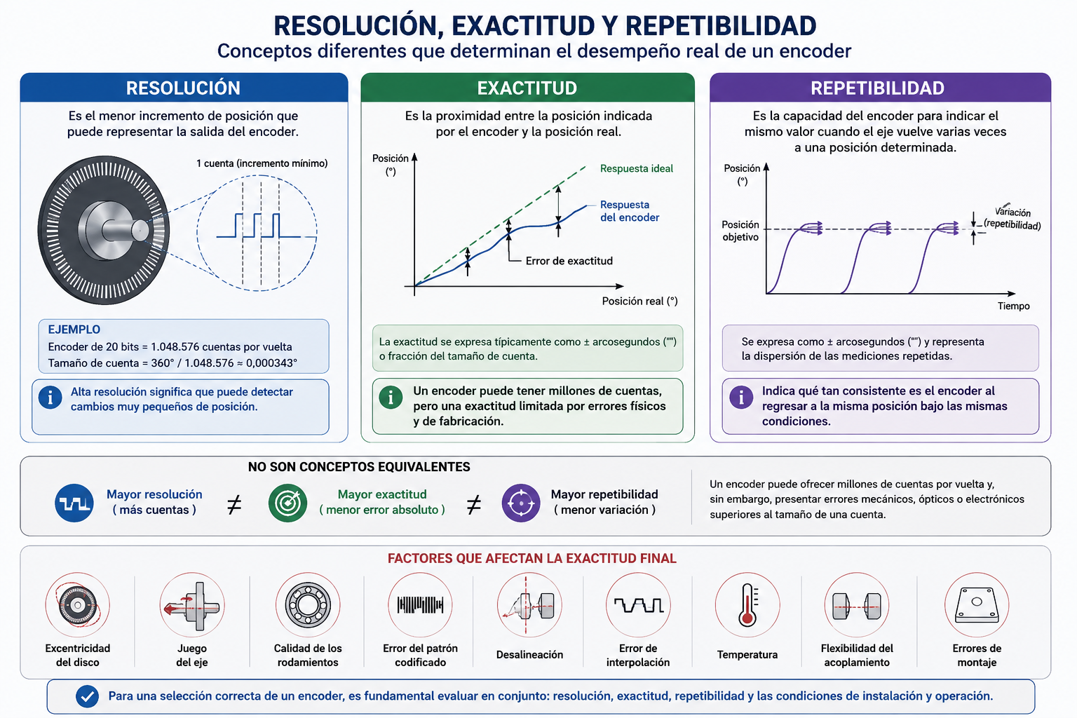
One of the most frequent mistakes when selecting an encoder is to assume that high resolution automatically implies high accuracy.
They are not equivalent concepts.
Resolution
It is the smallest position increment that the encoder output can represent.
Accuracy
It is the proximity between the position indicated by the encoder and the actual position.
Repeatability
It is the encoder's ability to indicate the same value when the shaft returns several times to a specific position.
Linearity
It indicates how much the relationship between the actual position and the measured position deviates from an ideal response.
An encoder can offer millions of counts per revolution and yet exhibit mechanical, optical, or electronic errors greater than the size of a count.
Final accuracy may be affected by:
- Eccentricity of the disc.
- Axle play.
- Bearing quality.
- Encoded pattern error.
- Misalignment.
- Interpolation error.
- Temperature.
- Coupling flexibility.
- Assembly errors.
How to calculate speed with an encoder
Speed can be calculated by counting the pulses during a time interval or by measuring the period between two consecutive pulses.
If an encoder generates N pulses per revolution and a frequency is measured f, The speed can be calculated using:
For example, for an encoder with 1,000 pulses per revolution and an output frequency of 20,000 Hz:
When using ×4 quadrature decoding, it must be correctly defined whether the N value represents pulses, periods, or counts.
At high speeds it is also necessary to check that the maximum output frequency does not exceed the input frequency allowed by the PLC, counter, drive or servo controller.
Output signals and interfaces
The encoder's internal technology should not be confused with its electrical interface.
Two optical encoders with a similar reading principle can use completely different outputs.
Incremental encoder outputs
- Push-pull.
- HTL.
- TTL.
- RS-422 differential line driver.
- Open collector.
- NPN.
- PNP.
- Sine and cosine of 1 Vpp.
- Differential signals A, /A, B, /B, Z and /Z.
Differential signals are especially recommended in long cables or environments with interference, because they allow the receiver to reject noise that affects both conductors similarly.
Absolute encoder interfaces
- Parallel output.
- SSI.
- BiSS-C.
- CANopen.
- SAE J1939.
- IO-Link.
- EtherCAT.
- PROFINET.
- EtherNet/IP.
- Proprietary interfaces for servomotors and drives.
The interface must be compatible with the driver and have a sufficient update speed for the dynamics of the application.
How to choose an encoder
The selection should begin with the mechanical and metrological needs of the application, and not just with the number of pulses or bits.
Type of movement
It must be determined whether it will be measured:
- Rotary motion.
- Linear motion.
- One lap only.
- Several laps.
- Relative position.
- Absolute position.
Resolution required
The resolution must be sufficient for the required control. Indiscriminately increasing the number of counts can increase output frequency and system load without improving actual accuracy.
Accuracy and repeatability
In positioning systems, the accuracy specified by the manufacturer must be checked, especially when mechanical reductions, gears or spindles are involved.
Maximum speed
It is necessary to verify:
- The maximum mechanical speed of the encoder.
- The maximum output frequency.
- The capacity of the counter.
- The PLC cycle time.
- The speed of the communication bus.
Axis type
The main mechanical formats are:
- Solid shaft.
- Hollow shaft.
- Hollow through shaft.
- Blind hollow shaft.
- Encoder without bearings.
- Modular encoder.
- Encoder kit for integration into motor.
Loads on the axis
The permissible radial and axial loads must not be exceeded. A flexible coupling is typically used to compensate for small misalignments without transmitting excessive stress to the bearings.
Environmental conditions
The following should be considered:
- Working temperature.
- Presence of dust.
- Water and humidity.
- Oil.
- Chemical products.
- Condensation.
- Vibration.
- Collisions.
- Magnetic fields.
- Risk of explosion.
- IP protection rating.
Power supply and output signal
Before connecting the encoder, the following must be checked:
- Supply voltage.
- Consumption.
- Output type.
- Logical level.
- Number of threads.
- Maximum cable length.
- Need for termination resistors.
- Maximum frequency.
- Receiver compatibility.
Why does an encoder get damaged or fail?
An encoder can fail due to mechanical, electrical, or environmental causes.
Shaft misalignment
Excessive misalignment places periodic loads on the bearings and can cause vibration, wear, and loss of accuracy.
Incorrect coupling
An overly rigid coupling transmits alignment errors, expansions, and axial displacements to the encoder.
Excessive radial or axial loads
The encoder shaft should not be used as a structural element or subjected directly to belts, gears, or stresses exceeding the permitted limits.
Excessive speed
Exceeding the maximum mechanical speed can damage the bearings. It's also possible that the encoder is functioning correctly, but the controller is unable to process the generated frequency.
Improper diet
An overvoltage, a polarity reversal, or an incorrect connection of the outputs can damage the internal electronics.
Electromagnetic interference
Encoder cables installed near motors, contactors, or drives may pick up interference.
To reduce them, it is advisable to use:
- Differential signals.
- Shielded cable.
- Twisted pairs.
- Separation from power cables.
- Proper grounding.
- Manufacturer's recommended finishes.
Pollution
In an optical encoder, dust, oil, or condensation can reduce the received light and cause distorted pulses or reading losses.
Water inlet
An insufficient IP rating, a poorly installed cable gland, or an unsealed connector can allow moisture to enter.
Shocks and vibrations
Impacts can damage bearings, the glass disk, magnetic elements, or reading systems.
Applications of encoders
Encoders are used whenever a system needs to relate physical movement to a control signal.
Some common applications are:
- Position control of servomotors.
- Feedback from electric motors.
- CNC machines.
- Industrial robots.
- Indexing tables.
- Elevators and freight elevators.
- Cranes and overhead cranes.
- Wind turbines.
- Antennas and telescopes.
- Motorized valves.
- Automatic storage systems.
- AGVs and mobile robots.
- Printing machinery.
- Packaging machines.
- Cutting and length measurement systems.
- Medical equipment.
- Test benches.
- Dimensional metrology.
- Conveyor belt speed control.
- Electronic axis synchronization.
Frequently asked questions about encoders
What is an encoder and what is it used for?
An encoder is a sensor that converts linear or rotary motion into an electrical signal. It is used to determine the position, displacement, speed, and direction of movement of a machine.
What does an encoder measure?
An encoder directly measures position or displacement. From its signal, velocity, direction of movement, and acceleration can also be calculated.
What is the difference between an encoder and a proximity sensor?
A proximity sensor typically detects the presence or absence of an object at a point. An encoder generates continuous information about movement or position along a path.
What is the difference between an incremental encoder and an absolute encoder?
The incremental encoder generates pulses that must be counted from a reference point. The absolute encoder directly outputs a code corresponding to the current position.
What do the signs A, B, and Z mean?
A and B are two quadrature signals used to count displacement and determine direction. Z is a reference pulse that typically appears once per revolution.
Which is better, an optical or a magnetic encoder?
It depends on the application. Optical encoders are usually chosen when high resolution and accuracy are required. Magnetic encoders are particularly suitable when dust, oil, humidity, or vibrations are present. The final quality depends on the specific design, not just the technology.
What does it mean for an encoder to have 1.024 PPR?
This typically means it generates 1,024 signal periods per revolution on each channel. Counting the four edges of A and B yields 4,096 counts per revolution. Always verify the nomenclature used by the manufacturer.
Does an absolute encoder need to perform homing?
Normally, you do not need to reference the encoder to determine its position within the absolute range. However, the machine may require initial calibration to relate the encoder value to the system's mechanical zero.
Can an encoder be used to measure speed?
Yes. Speed is obtained from the frequency of the pulses or the time elapsed between them.
Does an incremental encoder lose its position when disconnected?
The encoder remains physically in the same position, but the system may lose the value accumulated by the counter. For this reason, a reference search is usually necessary at startup.
Conclusion
An encoder is a position transducer that converts a linear or angular displacement into an electrical signal usable by a control system.
In a incremental encoder, The movement generates impulses that must be counted from a reference point. Channels A and B allow the direction of movement to be determined, while channel Z provides a reference mark, typically once per revolution.
In a absolute encoder, Each position is associated with a unique digital value. This allows the position to be retrieved directly upon connecting the device, without needing to reconstruct it by counting all previous movements.
Optical technology is notable for its resolution, accuracy, and repeatability, although it requires adequate protection against contamination, humidity, and vibrations. Magnetic, inductive, and capacitive technologies offer particularly interesting alternatives when environmental conditions are more demanding.
The correct selection of an encoder must take into account resolution, accuracy, speed, electrical interface, mechanical mounting, and actual operating conditions.
Selection of industrial encoders
Understanding how an encoder works allows you to correctly select its technology, resolution, output interface, and mounting system.
GUEMISA supplies incremental and absolute encoders for linear and angular position measurement in industrial applications.
To select the appropriate model, it is necessary to know, at a minimum, the type of movement, the resolution, the maximum speed, the mechanical format, the power supply, the output signal, and the environmental conditions of the installation.
Our technical department can study the application and propose a solution compatible with the control system and the mechanical requirements of the machine.
Consult us to select the most suitable encoder for your application.